
Page 32 - High Temperature Solid Oxide Fuel Cells Fundamentals, Design and Applications
P. 32
In troduction to SOFCs 13
difficulties arise because of the low toughness of the ceramic components and the
necessity of making eIectrical connections between all the cells.
Planar cells have the advantage that they can be readily electroded by screen
printing, they can be stacked together with narrow channels to achieve high
power densities and they can provide short current pathways through the
interconnect. If p is the power in Watts per square cm of membrane and g is
the gap in cm between planar electrolyte sheets, then the stack volumetric
power density is p/g kW/litre, typically 1 kW/litre for a Sulzer planar stack
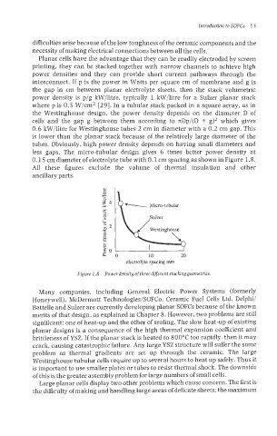
where p is 0.5 W/cm2 [29]. In a tubular stack packed in a square array, as in
the Westinghouse design, the power density depends on the diameter D of
cells and the gap g between them according to nDp/(D + g)2 which gives
0.6 BW/litre for Westinghouse tubes 2 cm in diameter with a 0.2 cm gap. This
is lower than the planar stack because of the relatively large diameter of the
tubes. Obviously, high power density depends on having small diameters and
less gaps. The micro-tubular design gives 6 times better power density at
0.15 cm diameter of electrolyte tube with 0.1 cm spacing as shown in Figure 1.8.
All these figures exclude the volume of thermal insulation and other
ancillary parts.
.- 3
T
Y $4
Micro-tubular
Y
8
+ Sulzer
L
~* 3 Westinghouse
8
v)
rn
8
b go o 10 20
electrolyte spacing mm
Figure 1.8 Power density ofthree tiifleerent stackinggeometries.
Many companies, including General Electric Power Systems (formerly
Honeywell), McDermott Technologies/SOFCo, Ceramic Fuel Cells Ltd, Delphi/
Battelle and Sulzer are currently developing planar SOFCs because of the known
merits of that design, as explained in Chapter 8. However, two problems are still
significant: one of heat-up and the other of sealing. The slow heat-up of existing
planar designs is a consequence of the high thermal expansion coefficient and
brittleness of YSZ. If the planar stack is heated to 800°C too rapidly, then it may
crack, causing catastrophic failure. Any large YSZ structure will suffer the same
problem as thermal gradients are set up through the ceramic. The large
Westinghouse tubular cells require up to several hours to heat up safely. Thus it
is important to use smaller plates or tubes to resist thermal shock. The downside
of this is the greater assembly problem for large numbers of small cells.
Large planar cells display two other problems which cause concern. The first is
the difficulty of making and handling large areas of delicate sheets; the maximum