
Page 142 - Hybrid Enhanced Oil Recovery Using Smart Waterflooding
P. 142
134 Hybrid Enhanced Oil Recovery using Smart Waterflooding
injection applications. Because of low thermal effi- water-alternating-steam process (WASP). The studies
ciency, extensive thermal energy is useless, and only a (Al-Saedi, Flori, Alkhamis, & Brady, 2018a,b) have
small fraction of energy is used to heat the target fluids. proposed the low salinityealternating steam flooding
(LSASF) process to combine the WASP and LSWF. The
experimental application of LSASF is evaluated to
STEAM INJECTION recover Kansas heavy oil from Berea sandstone cores.
Steam injection conventionally has several forms. The The four sets of coreflooding are conducted to investi-
main steam processes are cyclic steam stimulation and gate the tertiary recovery of LSASF. The steam tempera-
steam flooding. Conventionally, the cyclic steam stimu- ture is 150 C, and the experimental condition of
lation uses a single well for both injection and produc- temperature is the room temperature. The high saline
tion, and steam flooding is designed with multiwells for formation water has a salinity of 108,460 ppm TDS.
injector and producer. The cyclic steam stimulation The low salinity water is prepared by diluting the forma-
heats the oil and improves the mobilization of oil in tion water by a factor of 100.
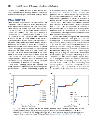
the vicinity of the well. The heated oil is produced by The first coreflooding is designed with the secondary
a number of driving forces, including the reservoir conventional waterflood, one cycle of LSASF, and
pressure depletion, gravity, formation compaction, etc. chasing LSWF. The secondary conventional water inject-
The steam flooding injects the steam into the reservoir ing formation water produces an oil recovery of about
and creates steam zones, in which the oil mobility is 42%. Then, the tertiary injection of LSASF follows the
affected. Because the steam has the tendency to migrate secondary injection. During the tertiary LSASF, the
toward the upper portion of formation due to gravity low salinity water injection and steam injection recover
segregation, the steam zones grow both laterally and the additional oil recovery of 2.8% and 1.86%, respec-
vertically. The heated and mobilized oil in the steam tively. The last chasing low salinity water injection after
zones is recovered through the producer. There are steam injection produces more oil recovery of 3.7%.
other variants of steam injection by modifying the The second and third coreflooding tests increase the cy-
two processes with additives addition, horizontal well, cle of LSASF process by two. The difference between the
conductive heating using fractures, etc. to overcome second and third coreflooding tests is the slug size
the inherent risks or improves the efficiency. injected. Both second and third coreflooding tests
The steam flooding shows the inherent low recover significant oil within the second cycle of LSASF
sweep efficiency due to early steam breakthrough and process (Fig. 6.4A). The ultimate oil recoveries are
gravity override. It can be improved by adapting the 57.8% and 62.7% for the second and third coreflooding
(A) (B)
70 70
60 60
50 50
Oil Recovery, % 40 FW Oil Recovery, % 40
30
30
LSW
Steam
20 LSW 20 FW
LSW LSW after Huff & Puff
10 Steam 10 Steam
LSW LSW
0 0
0 2 4 6 8 0 2 4 6 8
Injected Pore Volume Injected Pore Volume
FIG. 6.4 Heavy oil recovery of (A) low salinityealternating steam flooding process and (B) low
salinityealternating steam flooding with huff and puff process. (Credit: From Al-Saedi, H. N., Flori, R. E.,
Alkhamis, M., & Brady, P. V. (2018b). Coupling of low-salinity water flooding and steam flooding for sandstone
unconventional oil reservoirs. Natural Resources Research, https://doi.org/10.1007/s11053-018-9407-2.)