
Page 89 - Hybrid-Renewable Energy Systems in Microgrids
P. 89
Multilevel inverters: an enabling technology 73
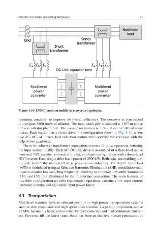
Figure 4.10 UPFC based on multilevel converter topologies.
operating condition to improve the overall efficiency. The conveyor is constructed
to transport 5800 ton/h of mineral. The mine stock pile is situated at 1307 m above
the concentrator plant level. The average inclination is 11% and can be 24% at some
places. Each section has a motor drive in a configuration shown in Fig. 4.11, where
two AC–DC–AC drives feed induction motors that supervise the conveyor with the
help of two gearboxes.
The delta-delta-wye transformer connection procures 12-pulse operation, bettering
the input current quality. Each AC–DC–AC drive is assembled of a three-level active
front-end NPC rectifier connected in a back-to-back configuration with a three-level
NPC inverter. Each single drive has a power of 2500 kW. Both sides are enabling dur-
ing gate turnoff thyristors (GTOs) as power semiconductors. The Active Front End
(AFE) is modulated using an Selective Harmonic Elimination (SHE) modulation tech-
nique to acquire low switching frequency, allowing to eliminate low-order harmonics
(11th and 13th) not eliminated by the transformer connection. The main features of
this drive configuration are fully regenerative operation, extremely low input current
harmonic content, and adjustable input power factor.
4.3 Transportation
Multilevel inverters have an relevant position in high-power transportation systems
such as ship propulsion and high-speed train traction. Large ship propulsion, above
25 MW, has mainly been predominated by cycloconverter and load commutated invert-
ers. However, till the latest years, there has been an decisive market penetration of