
Page 90 - Hybrid-Renewable Energy Systems in Microgrids
P. 90
74 Hybrid-Renewable Energy Systems in Microgrids
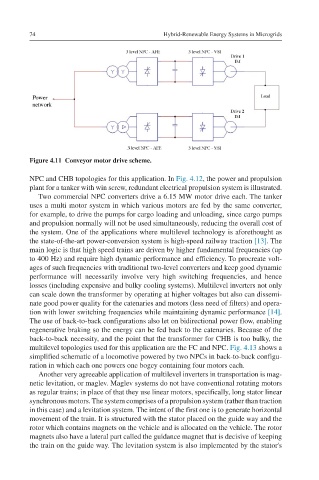
Figure 4.11 Conveyor motor drive scheme.
NPC and CHB topologies for this application. In Fig. 4.12, the power and propulsion
plant for a tanker with win screw, redundant electrical propulsion system is illustrated.
Two commercial NPC converters drive a 6.15 MW motor drive each. The tanker
uses a multi motor system in which various motors are fed by the same converter,
for example, to drive the pumps for cargo loading and unloading, since cargo pumps
and propulsion normally will not be used simultaneously, reducing the overall cost of
the system. One of the applications where multilevel technology is aforethought as
the state-of-the-art power-conversion system is high-speed railway traction [13]. The
main logic is that high speed trains are driven by higher fundamental frequencies (up
to 400 Hz) and require high dynamic performance and efficiency. To procreate volt-
ages of such frequencies with traditional two-level converters and keep good dynamic
performance will necessarily involve very high switching frequencies, and hence
losses (including expensive and bulky cooling systems). Multilevel inverters not only
can scale down the transformer by operating at higher voltages but also can dissemi-
nate good power quality for the catenaries and motors (less need of filters) and opera-
tion with lower switching frequencies while maintaining dynamic performance [14].
The use of back-to-back configurations also let on bidirectional power flow, enabling
regenerative braking so the energy can be fed back to the catenaries. Because of the
back-to-back necessity, and the point that the transformer for CHB is too bulky, the
multilevel topologies used for this application are the FC and NPC. Fig. 4.13 shows a
simplified schematic of a locomotive powered by two NPCs in back-to-back configu-
ration in which each one powers one bogey containing four motors each.
Another very agreeable application of multilevel inverters in transportation is mag-
netic levitation, or maglev. Maglev systems do not have conventional rotating motors
as regular trains; in place of that they use linear motors, specifically, long stator linear
synchronous motors. The system comprises of a propulsion system (rather than traction
in this case) and a levitation system. The intent of the first one is to generate horizontal
movement of the train. It is structured with the stator placed on the guide way and the
rotor which contains magnets on the vehicle and is allocated on the vehicle. The rotor
magnets also have a lateral part called the guidance magnet that is decisive of keeping
the train on the guide way. The levitation system is also implemented by the stator's