
Page 178 - Hydrocarbon Exploration and Production Second Edition
P. 178
Reservoir Description 165
Dual Laterolog Tool Induction Tool
focussed
current
receiver
measured I
current
induced
current
transmitter
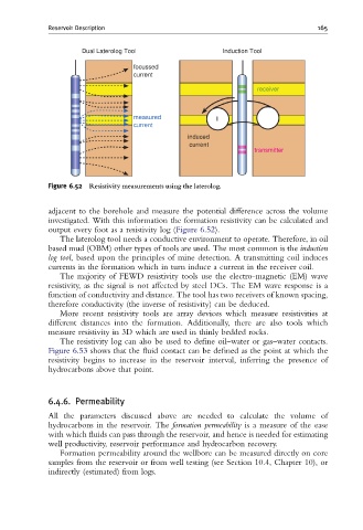
Figure 6.52 Resistivity measurements using the laterolog.
adjacent to the borehole and measure the potential difference across the volume
investigated. With this information the formation resistivity can be calculated and
output every foot as a resistivity log (Figure 6.52).
The laterolog tool needs a conductive environment to operate. Therefore, in oil
based mud (OBM) other types of tools are used. The most common is the induction
log tool, based upon the principles of mine detection. A transmitting coil induces
currents in the formation which in turn induce a current in the receiver coil.
The majority of FEWD resistivity tools use the electro-magnetic (EM) wave
resistivity, as the signal is not affected by steel DCs. The EM wave response is a
function of conductivity and distance. The tool has two receivers of known spacing,
therefore conductivity (the inverse of resistivity) can be deduced.
More recent resistivity tools are array devices which measure resistivities at
different distances into the formation. Additionally, there are also tools which
measure resistivity in 3D which are used in thinly bedded rocks.
The resistivity log can also be used to define oil–water or gas–water contacts.
Figure 6.53 shows that the fluid contact can be defined as the point at which the
resistivity begins to increase in the reservoir interval, inferring the presence of
hydrocarbons above that point.
6.4.6. Permeability
All the parameters discussed above are needed to calculate the volume of
hydrocarbons in the reservoir. The formation permeability is a measure of the ease
with which fluids can pass through the reservoir, and hence is needed for estimating
well productivity, reservoir performance and hydrocarbon recovery.
Formation permeability around the wellbore can be measured directly on core
samples from the reservoir or from well testing (see Section 10.4, Chapter 10), or
indirectly (estimated) from logs.