
Page 301 - Hydrogeology Principles and Practice
P. 301
HYDC08 12/5/05 5:31 PM Page 284
284 Chapter Eight
upstream river needs have been met and so any
surplus water that would otherwise be lost to tidal
waters and eventually to the Wash is potentially
available for transfer. The Impounding Sluice gate
at Denver is designed to enable the water level in
the river channel to be raised approximately 0.6 m,
thereby producing a reversal of flow. The water is
sent in a reverse direction approximately 25 km
south-east to the Blackdyke Intake. Here it is drawn
off into a 20-km-long tunnel which terminates at
Kennett whereupon the water is pumped through a
14.3-km-long pipeline to the River Stour at Kirtling
Green. Part of this discharge is drawn off at Wixoe,
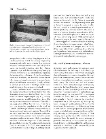
Fig. 8.4 Transfer of water from the Ely Ouse River to the Cut-Off
13.7 km downstream and pumped 10.3 km to the
Channel at Denver. Water transferred from here travels to
Abberton and Hanningfield reservoirs in support of water supply River Pant. The water transferred from Denver
and river flows in the drier south-east of England (Fig. 8.2). travels 141 km to Abberton reservoir and 148 km to
Hanningfield reservoir. For two-thirds of these dis-
tances, use is made of exiting watercourses.
was predicted to be 4 m in a drought period with a
1 in 50-year return period. Such a large engineering
programme of works was not carried forward partly 8.2.4 Artificial storage and recovery schemes
because of conflicts with other users for Chalk ground-
water, for example irrigation water for valuable As surface water and groundwater schemes reach
vegetable crops, and also the change in philosophy full development, the final stage is artificial recharge
towards protection of the environment, especially where water, often treated wastewater, is recharged
the Breckland Meres, from the effects of groundwater through basins and returned to the aquifer. Although
drawdown. However, the boreholes drilled for the practised in other countries, often on an uncontrolled
pilot study are today incorporated in a much larger basis and potentially threatening longer-term ground-
scheme, the Ely Ouse Essex Water Transfer Scheme, water quality (for example in China and Mexico;
to provide groundwater to the large public water Foster et al. 1999), artificial recharge is not typically
supply demand in the south-east of England. practised in the United Kingdom where treated water
The Ely Ouse Essex Water Transfer Scheme enables is returned to rivers from sewage treatment works.
the transfer of surplus water from the Ely Ouse (the A relatively recent development of artificial recharge
River Great Ouse) to the heads of Essex rivers in the is aquifer storage and recovery (ASR) to meet peak
south-east of the Anglian region (Fig. 8.2), thereby demands for water. The ASR technique, shown
making extra water available to the Essex rivers. The schematically in Fig. 8.5, works on the principle of
county of Essex experiences conditions of low effect- using boreholes to recharge drinking water-quality
−1
ive precipitation of less than 125 mm a , yet has a water into aquifers and to subsequently recover the
large and expanding population to the north of stored water from the same boreholes during times
London. One of the great merits of the scheme is that of peak demand or drought periods. Such schemes
it augments existing reservoir capacity, thus avoiding operate by displacing the native groundwater, effect-
the loss of agricultural land to create new reservoirs. ively creating an underground reservoir of near
Under the scheme, surplus water from the eastern drinking water-quality water. The volume of water
part of the catchment, including Chalk groundwater recovered from the aquifer for supply purposes is
resources available for regulation of the westward generally close to but not more than the volume
flowing Chalk rivers (the Rivers Lark, Little Ouse and injected (Eastwood & Stanfield 2001). ASR schemes
Thet), is transferred to the flood protection scheme are therefore considered to offer a sustainable means
Cut-Off Channel at Denver (Fig. 8.4). At this point, all of groundwater development.