
Page 216 - Improving Machinery Reliability
P. 216
Machinery Reliability Audits and Reviews 187
Step I: Collect data
P,, = transmitted horsepower
np = pinion rpm
d = pinion pitch diameter, in.
F = net face width of the narrowest of the mating gears or the sum of the
face widths of each helix of double helical, in.
mG = gear ratio
A = pressure angle
H, = gear hardness
L = net face width and gap
9 = helix angle
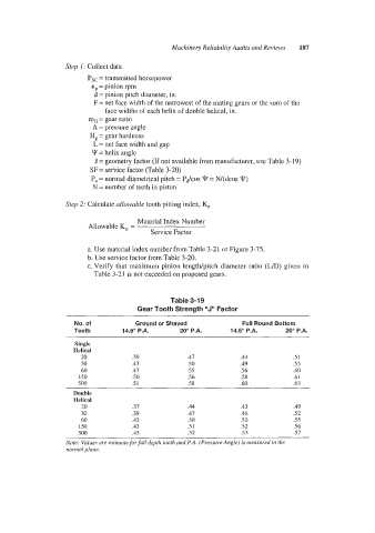
J = geometry factor (If not available from manufacturer, use Table 3- 19)
SF = service factor (Table 3-20)
P, = normal diametrical pitch = P&os T = N/(dcos 9)
N = number of teeth in piston
Step 2: Calculate allowable tooth pittirig index, KO
Material Index Number
Allowable KO =
Service Factor
a. Use material index number from Table 3-21 or Figure 3-75.
b. Use service factor from Table 3-20.
c. Verify that maximum pinion length/pitch diameter ratio (L/D) given in
Table 3-21 is not exceeded on proposed gears.
Table 3-19
Gear Tooth Strength "J" Factor
____
~ ~ ~ ~~
No. ob Ground or Shaved Full Round Bottom
Teeth 14.5" P.A. 20" P.A. 14.5" P.A. 20" P.A.
Single
Helical
20 .39 .41 .44 .5 I
30 .43 .50 .49 .55
60 .47 .55 .56 60
I50 .50 .56 .58 .6 I
500 .5 1 .58 .60 .63
Double
Helical
20 .31 .44 .43 .49
30 .39 .47 .46 .52
60 .42 SO .50 .55
I50 .43 .5 1 52 .56
500 .45 .52 .53 .51
Note: Vnlttes (ire estiiirate forjidl depth tooth nrid P.A. (Pressure Angle) is rtrensicretl in the
iiortml plane.