
Page 217 - Improving Machinery Reliability
P. 217
188 Improving Machinery Reliability
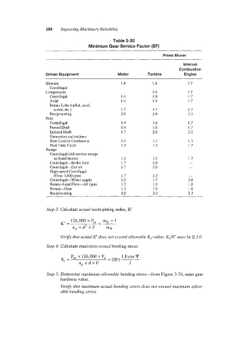
Table 3-20
Minimum Gear Service Factor (SF)
Prime Mover
Internal
Combustion
Driven Equipment Motor Turbine Engine
Blowers 1.4 1.6 1.7
Centrifugal
Compressors 1.6 I .7
Centrifugal 1.4 1.6 I .I
Axial 1.4 1.6 1.7
Rotary Lobe (radial, axial,
screw, etc.) 1.7 1.7 1.7
Reciprocating 2.0 2.0 2.3
Fans
Centrifugal 1.4 I .6 1.7
Forced Draft 1.4 I .6 I .7
Induced Draft I .7 2.0 2.2
Generators and exciters
Base Load or Continuous 1.1 1.1 I .3
Peak Duty Cycle 1.3 I .3 I .7
Pumps
Centrifugal (All service except
as listed below) 1.3 I .5
Centrifugal-Boiler feed I .7 2.0
Centrifugal-Hot oil 1.7 2.0
High-speed Centrifugal
(Over 3,600 rpm) 1.7 2.0 -
Centrifugal-Water supply I .5 1.7 2.0
Rotary-Axial Flow-All types 1.5 1.5 1.8
Rotary-Gear 1.5 1.5 I .8
Reciprocating 2.0 2.0 2.3
Step 3: Calculate actual tooth pitting index, K'
126,000 x P,, mG + 1
K'= X-
n,xd2xF mG
Verify that actual K' does not exceed allowable KO-value: KJK' must be Z 1.0.
Step 4: Calculate maximum actual bending stress
Psc x 126,000 x P, 1.8 cos Y
s, = x(SF)
npxdxF
Step 5: Determine maximum allowable bending stress-from Figure 3-76, enter gear
hardness value.
Verify that maximum actual bending stress does not exceed maximum allow-
able bending stress.