
Page 214 - Improving Machinery Reliability
P. 214
Machinery Reliability Audits and Reviews 185
Cf: The surface-condition factor takes into account tooth surface finish and resid-
ual stress. Generally, it is taken as 1. However, it may go to about 1.25 for
rough finishes that would cause localized contacts, or when residual stresses
are expected to be high or unpredictable. Both conditions can warrant a value
as high as 1 SO; this would derate gear life about 35 times.
Cm: The load distribution factor allows for anything that might prevent 100%
gear-tooth contact: lead and profile errors, stiffness of gears and mountings,
deviations from true alignment of the gear axis, and uneven thermal expan-
sion during operation. If all such conditions were ideal, C, would be 1 .00; but
practical conditions may drive this value to 3.00 or more. For a value of 3.00,
gear life would be derated 1,530 times.
Experience shows that wide-face gears require special considerations to off-
set net misalignment and to obtain good load distribution at full torque. Gener-
ally, a face width equal to the pinion diameter is the best compromise.
It should be remembered that misalignment cannot be readily absorbed by
the gear teeth except through plastic deformation, which is difficult to predict
in terms of life. Extreme profile modifications in a helical mesh can reduce
instantaneous lines of contact to nearly point contacts; this is as bad as severe
misalignment. Usually a few ten thousandths addendum relief is enough to
assure a smooth load transfer from tooth to tooth.
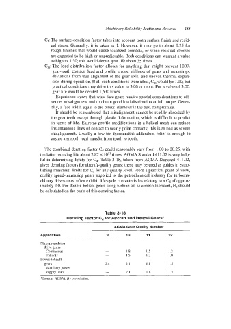
The combined derating factor Cd could reasonably vary from 1.00 to 20.25, with
the latter reducing life about 2.87 x 10" times. AGMA Standard 41 1.02 is very help-
ful in determining limits for Cd. Table 3-18, taken from AGMA Standard 41 1.02,
gives derating factors for aircraft-quality gears: these may be used as guides in estab-
lishing minimum limits for Cd for any quality level. From a practical point of view,
quality speed-increasing gears supplied to the petrochemical industry for turboma-
chiiiery drives most often exhibit life-cycle characteristics relating to a Cd of approx-
imately 2.0. For double-helical gears using turbine oil as a mesh lubricant, N, should
be calculated on the basis of this derating factor.
Table 3-18
Derating Factor Cd for Aircraft and Helical Gears*
-
AGMA Gear Quality Number
Application 9 IO 11 12
~ ____~~
Main propulsion
drive gears
Continuous - 1.8 1.5 1.2
Takeoff - 1.5 I .2 I .o
Power-takeoff
gears 2.4 2.1 1.8 I .5
Auxiliary power
supply units - 2. I I .8 1.5
*Source: AGMA. By pentiissioti.