
Page 213 - Improving Machinery Reliability
P. 213
184 Improving Machinery Reliability
GEAR HARONESS ~ H~NIMUM ann GEAR HARDNESS ~ ROCKWELL C
om
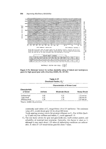
VALUES ARE 10 BE TnKEIl FROM THE ABOVE CURVE fOR THE MINIMUM HARDIIESS SPEClflED FOR IHE GEAR
VALUES FOR SUGGLSTEO GEAR AND PlNlOH HARDNESS COMBINATIONS ARC 1ABULAlLO BELOW FOR CONVENIENCL
PIMON AN0 GEAR MAY BE THE S4ME HARDNESS WHEN THE GE4R RATIO IS I5 OR LESS ow
2
2
MATERIALS FACTOR FOR STEEL- (:;S -
Figure 3-74. Materials factors for surface durability rating of helical and herringbone
gears for high-speed gear units. (Courtesy AGMA, No. 421.06.)
Table 3-17
Overload Factor, C,*
Characteristic of Driven Load
Characteristic
of Driver Uniform Moderate Shock Heavy Shock
Uniform load 1 .oo 1.25 1.75 und up
Light shock I .25 1.50 2.00 and up
Medium shock 1 SO I .I5 2.25 and up
*Source: AGMA. By permission.
commonly used values of C, ranged from 1.0 to 0.5 and lower. The minimum
value of C, would derate gear life by about 440 times.
Tooth-spacing accuracy exerts the greatest influence on C,. For AGMA Quali-
ty 12 and very low stiffness and inertia, C, could approach 1 .O.
C,: The size factor allows for gear and gear-tooth size, tooth-contact pattern, and
reliability of material heat treatment. Generally, this factor is taken as 1,
although it may reach about 1.25 when all influencing conditions are unfavor-
able. A value of 1.25 would derate gear life about 7 times.