
Page 260 - Improving Machinery Reliability
P. 260
Mrichiriery Reliability Audits arid Reviews 231
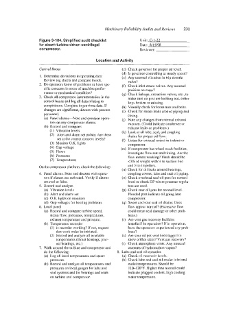
Figure 3-104. Simplified audit checklist Unit: C-1-22
for steam turbine driven centrifugal Date: 8/15/98
compressor. Reviewer:
Location and Activity
Coorrtrol Rooni (c) Check governor for proper ail level.
(d) Is governor controlling at steady speed?
1. Determine deviations in operating data: (e) Any unusual vibration in trip throttle
Review log sheets and compare trends. valve?
2. 110 operators know of problems or have spe- (f) Check inlet steam valves. Any uousual
cific concerns in areas of machine perfor- position on cams?
mance or mechanical condition? (g) Check linkage, extraction valves, etc., to
3. Check all compressor instrumentation in the make sure no pins are backing out, cotter
control house and log all data relating to keys broken or missing.
compressors. Compare to previous data. If (h) Visually check for loose nuts and bolts.
changes are significant, discuss with process (i) Check for steam leaks around piping and
personnel. casing.
(a) Panel alarms-Note and question opera- (j) Note any changes from normal exhaust
tors on any compressor alarms. vacuum. (Could indicate condenser or
(b) Record and compare: exhaust leaks or problems.)
(I) Vibration levels (k) Look at all lube, seal, and coupling
(2) Alert and alarm set points: Are these drains for proper oil flow.
set at the correct concern levels? (I) Listen for unusual noises in turbine or
(3) Monitor O.K. lights compressor.
(4) Gap voltage (m) If compressor has wheel wash facilities,
(5) Flows investigate flow rate and timing. Are the
(6) Pressures flow meters working? Flush should be
(7) Temperatures <3% of weight with H to suction line
On the compressor platform, check the following: and H to impellers.
(11) Check for oil leaks around hearings,
4. ]Panel alarms. Note and discuss with opera- coupling covers, lube and seal oil piping.
!tors if alarms are activated. Verify if alarms (0) Check overhead seal oil pots for normal
are real or false. level or check DP where pressure regula-
5. Record and analyze tors are used.
(a) Vibration levels (p) Check sour oil pots for normal level.
(b) Alert and alarm set Flooded pots indicate oil going into
(c) O.K. lights on monitors compressor.
(d) Gap voltages for bearing problems (9) Sweet and sour seal oil drains: Does
6. Local panel flow appear normal? (Excessive flow
(a) Record and compare turbine speed, could mean seal damage or other prob-
steam flaw, pressures, temperatures, lems.)
exhaust temperature and pressure. (r) Are vent gas recovery facilities
(b) Temperature recorder installed? In operation? If in operation,
(1) Is recorder working? If not, request have the operators experienced any prob-
that work order be initiated. lems?
(2) Record and analyze all available (s) Are sour oil pot vent lines tagged to
temperatures (thrust bearings, jour- show orifice sizes? Vent gas recovery?
nal bearings, etc.) (t) Check atmosphere vents. Any unusual
7. Walk around the turbine and compressor and amounts of hydrocarbon vapors?
do the following: 8. Lube and seal oil consoles
(a) Log all local temperatures and steam (a) Check oil reservoir levels.
pressures. (b) Check lube and seal oil cooler inlet and
(b) Record and analyze all temperatures and outlet temperatures. Should be
pressures on local gauges for lube and 110-120°F. Higher than normal could
seal systems and for bearings and seals indicate plugged coolers, high cooling
on turbine and compressor. water temperature.