
Page 103 - Industrial Power Engineering and Applications Handbook
P. 103
5/84 Industrial Power Engineering and Applications Handbook
The starting time may be shorter or longer depending
upon the load. The disadvantage is that if for any reason,
say, as a result of excessive load due to friction or
momentary obstructions if the motor takes a longer time
to pick up, the second contactor will not close until the
motor has picked up to a certain speed, and may thus
create a false stalling condition and allow persistence of
a higher starting current. In a 'definite time' start the
other contactor will close after a pre-set definite time,
cutting a piece of external resistance and hence increasing
the torque, giving the motor a chance to pick up. Thus,
only this method is normally employed for modem slip-
ring motor starts and controls. Below we will describe
only with this type of control. Speed - c L g
5.2.1 Selection of rotor resistance
Smax
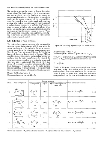
The choice of the external resistance to be introduced in
the rotor circuit during start-up will depend upon the Figure 5.1 Operating region of torque and current curves
torque requirement or limitation in the stator current,
without jeopardizing the minimum torque requirement.
Since T,, and Ist are interrelated (Section 2.4) limitation Rotor standstill voltage = ,,e2
in one will determine the magnitude of the other. Making Rotor voltage at a particular speed = RV = S . sse2
use of the circle diagram or the torque and current curves Then, for a stator current of Zrl, corresponding to a starting
available from the motor manufacturer, the value of the torque of T,,,, the required rotor current will be
stator current corresponding to a particular torque and
vice versa can be determined. The slip at which this IF1
torque will occur on its operating region can also be found I,1 = - 'I,
I,
from these curves (Figure 5.1). For this stator current,
the corresponding rotor current can be ascertained and To obtain this rotor current, the required rotor circuit
the rotor circuit resistance calculated to obtain this current. resistance can be calculated as below for the various
configurations of the rotor windings and the resistance
If stator full load current = I, units. It may be noted that, when the resistance
Corresponding rotor current RA = I, configuration is not the same as that of the rotor, it must
External resistance
SI. no. Rotor configuration Total rotor circuit resistance
Equivalent configurations
of the rotor
3 R p y
'he ~
3 sse2 R2 5.2(c) (5.1~)
Re
sse2 :+q 'Ae
4 ZRz 5,2(d)
R2 Re