
Page 106 - Industrial Power Engineering and Applications Handbook
P. 106
Starting and control of slip-ring induction motors 5/87
Example 5.2 speeds) is of little consequence. In such starters, there is
A 125 kW, 41 5 V, 3@ wound rotor has the following parameters: no control over the time of start or resistance in the
l, = 230 A circuit (torque at different speeds) during the start-up
period. Liquid rotor starters are one type and are suitable
sse2 = 500 V only for light duties. For heavy loads, requiring specific
I,, = 180 A torque values during pick-up, specific resistances must
be introduced into the rotor circuit at specific speeds.
Tpo = 250% The specific resistances so required can be determined
R2 = 0.09 ohm (star connected) as discussed below and manufactured in the form of a
grid. These resistance grids are then controlled through
The torque and current curves are as shown in Figure 5.4. contactors and timers. The duration between each step
Determine the external resistance required to achieve a starting of the resistance grid is pre-determined, the torque demand
torque of 200%. is already ascertained and the resistance required at each
step is pre-calculated. The starter can then be made
Solution
From these curves, for a torque of 200% the stator current pushbutton-operated fully automatic. With the help of
should be 250%, Le. 230 x 2.5 A. pre-set timers at each step, the entire resistance is cut off
:. Corresponding rotor current, gradually and automatically, maintaining the pre-
determined torque profile.
180
x
I,,, - 230 x 2.5 A
230
= 180 ~2.5 5.2.2 Determining external resistance and
A
time of start
and rotor circuit resistance, with a star-connected resistance
unit, Consider Figure 5.5 with six steps (rotor resistance unit
with five steps) and assume the maximum and minimum
R2, = & 500 torques as T,,, and Tmin between each step, to suit a
x 180 x 2.5 particular load demand (Figure 5.6(a)). Let the
= 0.641 corresponding rotor currents be I,,, and Imin. Then by a
simple hypothesis using equation (I .7).
:. External resistance required, Re = 0.641 - 0.09
= 0.551 R per phase
Method of cutting off the external resistance
The simplest method is performing it manually. Once
the total external resistance is known, the resistance unit
can be built with a hand-operated mechanism to manually
cut-off the external resistance. However, this method is
suitable only for applications where the magnitude of
torque during the pick-up period (torque at different lR2
'r18
Rotor -Y
Shorted
during run
e R2 1
2
co 5-step external
rotor resistance
T,-1
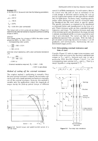
Speed + Star connected
resistance
Figure 5.4 Speed-torque and speed-current curves of a
125 kW motor Figure 5.5 Five-step rotor resistance