Page 108 - Industrial Power Engineering and Applications Handbook
P. 108

Starting and control of slip-ring induction motors  5/89


                                                                     C

                                                                                T


                                                                     35   dl    Id2   /d3   d4   d


                              d5
                                                                                                d2


                              d4


                              d3
                                                                                            I
                                                            C
                                       uj
                                       d
                              d2


                              dl
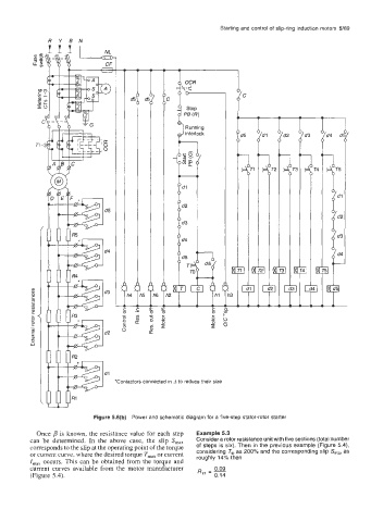
                                 ‘Contactors  connected in A to reduce their size


                           Figure 5.6(b)  Power and schematic diagram for a five-step stator-rotor starter

           Once p is known, the  resistance value for each step   Example 5.3
         can  be  determined. In  the  above  case,  the  slip S,,,   Consider a rotor resistance unit with five sections (total number
         corresponds to the slip at the operating point ofthe torque   of steps is Six). Then in the previous example (Figure 5.4),
         or current curve, where the desired torque T,,,  or current   considering  Tst as 200% and the corresponding slip Sm, as
                                                        roughly 14% then
         I,,,  occurs. This can be obtained from the  torque and
         current curves available from  the  motor manufacturer   - 0.09
         (Figure 5.4).                                    21  - -
                                                             0.14
   103   104   105   106   107   108   109   110   111   112   113