
Page 113 - Industrial Power Engineering and Applications Handbook
P. 113
5/94 Industrial Power Engineering and Applications Handbook
Y To achieve a better torque, the slip-ring rotors are normally
wound in star, in which case the rotor current is 8 time
more than in delta for the same output. Also since the
torque is proportional to the rotor current equation (1. 1),
the torque developed will be greater in this case.
Example 5.5
For the 125 kW motor of Example 5.2, if a speed reduction is
required by 50% at constant torque (see also Figure 6.51)
and the rotor current is now 73% of its rated value (Table
5.3), then the total rotor circuit resistance
- 500~0.5
- x 180 x 0.73
= 1.098 !2
and external resistance
Re = 1.098 - 0.09
or 1.008 Q
5.5 Moving electrode electrolyte
0 starters and controllers
4 %Speed-
Shaded portion indicates power loss in the rotor circuit
5.5.1 As a rotor resistance for slip-ring motors
Figure 5.8 Variation in torque and output with speed These are similar to stator resistance starters, as discussed
in Section 4.2.3 and can be used in the rotor circuit to
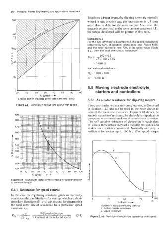
control the rotor side resistance. Figure 5.10 shows the
smooth variation of resistance by electrolytic vaporization
compared to a conventional metallic resistance variation.
The self-variable resistance of electrolyte is equivalent
to almost three or four steps of a metallic resistance and
makes such starters economical. Normally one step is
sufficient for motors up to 160 h.p. (For speed-torque
0 10 20 30 40 50 60 70 80 90 100
% Speed- 4
Figure 5.9 Multiplying factor for motor rating for speed variation
at constant torque
5.4.1 Resistance for speed control
In this case the regulating resistance grids are normally
continuous duty, unlike those for start-up, which are short- 0 25 50 75 '1 )O
time duty. Equations (5.1 a-d) can be used, for determining % Speed- Nr
the total rotor circuit resistance for a particular speed Variation in resistance during starting
variation, i.e. 1. 3-Step metallic resistance
2. Liquid electrolyte
R21 =-' ss e2 %Speed reduction (5.4) Figure 5.10 Variation of electrolyte resistance with speed
2/7. I, %Current at the reduced speed