
Page 109 - Industrial Power Engineering and Applications Handbook
P. 109
5/90 Industrial Power Engineering and Applications Handbook
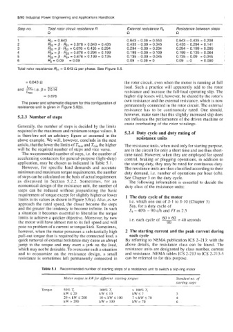
Step no. Total rotor circuit resistance R External resistance Re Resistance between steps
R R R
1 R2j = 0.643 0.643 - 0.09 = 0.553 0.643 - 0.435 = 0.208
2 R22 = p. R21 = 0.676 x 0.643 = 0.435 0.435 - 0.09 = 0.345 0.435 - 0.294 = 0.141
3 R23 = p. R22 = 0.676 x 0.435 = 0.294 0.294 - 0.09 = 0.204 0.294 - 0.199 = 0.095
4 1324 = /?. R23 = 0.676 x 0.294 = 0.199 0.199 - 0.09 = 0.109 0.199 - 0.135 = 0.064
5 R25 = p. R24 = 0.676 X 0.199 = 0.135 0.135 - 0.09 = 0.045 0.1 35 - 0.09 = 0.045
6 R2 = 0.09 = 0.09 0.09 - 0.09 = 0 0.09 - 0 = 0.090
Total rotor resistance R2, = 0.643 R per phase. See Figure 5.5
= 0.643 R the rotor circuit, even when the motor is running at full
load. Such a practice will apparently add to the rotor
and i.e. p =
Illlax resistance and increase the full-load operating slip. The
= 0.676 higher slip losses will, however, be shared by the rotor’s
own resistance and the external resistance, which is now
The power and schematic diagram for this configuration of permanently connected in the rotor circuit. The external
resistance unit is given in Figure 5.6(b).
resistance has to be continuously rated. One should,
however, make sure that this slightly increased slip does
5.2.3 Number of steps not influence the performance of the driven machine or
cause overheating of the rotor windings.
Generally, the number of steps is decided by the limits
required in the maximum and minimum torque values. It 5.2.4 Duty cycle and duty rating of
is therefore not an arbitrary figure as assumed in the resistance units
above example. We will, however, conclude in the next
article, that the lower the limits of T,,, and Tmin the higher The resistance units, when used only for starting purpose,
will be the required number of steps and vice versa. are in the circuit for only a short time and are thus short-
The recommended number of steps, i.e. the number of time rated. However, when they are employed for speed
accelerating contactors for general-purpose (light-duty) control, braking or plugging operations, in addition to
application, may be chosen as indicated in Table 5.1. the starting duty, they may bc rated for continuous duty.
However, for specific load demands and accurate The resistance units are thus classified according to their
minimum and maximum torque requirements, the number duty demand, Le. number of operations per hour (c/h).
of steps can be calculated on the basis of actual requirement See Chapter 3 on the duty cycle.
as discussed in Section 5.2.2. Sometimes, for an The following information is essential to decide the
economical design of the resistance unit, the number of duty class of the resistance units:
steps can be reduced without jeopardizing the basic
requirement of torque except for slightly higher or lower 1 The duty cycle of the motor
limits in its values as shown in Figure 5.6(a). Also, as we i.e. which one out of S-1 to S-10 (Chapter 3)
approach the rated speed, the closer become the steps Say, for a duty cycle of
and the greater the tendency to become infinite. In such S4 - 40% - 90 c/h and FI as 2.5
a situation it becomes essential to liberalize the torque
limits to achieve a quicker objective. Moreover, by now i.e. each cycle of 6o 6o - 40 seconds
-
the motor will have almost run to its full speed and will ~ 90
pose no problem of a current or torque kick. Sometimes,
however, when the motor possesses a substantially high 2 The starting current and the peak current during
pull-out torque than is required by the connected load, a each cycle
quick removal of external resistance may cause an abrupt By referring to NEMA publication ICs 2-213: with the
jump in the torque and may exert a jerk on the load, above details, the resistance class can be found. The
which may not be desirable. To overcome such a situation resistance units are designated by class number, current
and to economize on the resistance design, a small and resistance. NEMA tables ICs 2-213 to ICs 2-213-5
resistance is sometimes left permanently connected in can be referred to for this purpose.
Table 5.1 Recommended number of starting steps of a resistance unit to switch a slip-ring motor
Motor output in kW for different starting torques Standard no. of
starting steps
Torque 50% T, 100% T, > 100% T,
kW I20 kW I 10 kWI7 3
20 < kW I 200 10 < kW S 100 7 < kW I 70 4
kW > 200 kW > 100 kW > 70 6