
Page 98 - Industrial Power Engineering and Applications Handbook
P. 98
Starting of squirrel cage induction motors 4/79
2 It is important to maintain the level of the electrolyte however, be comparable with autotransformer
to retain the desired characteristics on a repeat start. switching.
However, this may be necessary only once a year as
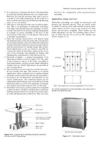
a result of very little evaporation. In the event of a Application, ratings and sizes
lower level the electrolyte can be filled up with drinking
water, as in a car battery. Electrolyte switchings are simple in construction and
3 This type of switching provides very smooth accelera- possess high thermal capacity. They are ideally suited
tion. This is an advantage of electrolyte switchings for difficult starting duties and remotely located plants,
over other conventional types of switchings. It exerts where expert services, such as are required for static
no kicks and calls for no special coupling arrangement drives, are not easily available. These starters are not
to transmit the power smoothly to the drive if the bulky and rating is no bar. The common range is from 1
requirement of the drive is to be precise and to have h.p. to 1000 h.p. for LT as well as HT squirrel cage
a smoother acceleration. motors (Figure 4.1 1).
4 Since the starting characteristics will depend upon
the initial resistance of the electrolyte, the concentration
of electrolyte and the active area of the electrode must
be determined beforehand for a particular type of drive,
and the requirements of starting torque and current.
Small adjustments at site are, however, possible by Connection
varying the depth of electrodes, adjusting the active
area of the electrode, repositioning the flanges and
changing the concentration of the electrolyte etc. F+
5 Electrode assembly - a general arrangement of an Unit first-
electrode assembly is shown in Figure 4.10. The value
of the resistance is preset at the works, according to L
load requirements, starting current, torque limitation,
starting time etc. Small adjustments are possible at Unit second-
site as noted above.
6 The electrolytes are non-corrosive and the electrodes
do not corrode with time. This feature is of special
significance when compared with an ordinary liquid
resistance starter used commonly for slip-ring motors.
7 Electrolytes do not deteriorate and therefore do not
require replacement. The evaporated liquid can be
replenished with drinking water when the level of the
electrolyte falls as a result of evaporation. In Europe
such starters have been used for over 15-20 years. Note One single unit is normally designed for 10 to 40 H.P.
8 Electrolyte switching is a costlier proposition compared
to direct on-line or staddelta switching due to additional (a) Typical arrangement of two electrolyte units being used in
shorting contactor and timer, and the cost of electrolyte, parallel one above the other
its tank and thermostatic control etc. The cost may,
Electrode
Tank cover
Regulating insulation
Electrode for electrolyte
level indicating lamps
Nylon flanges
Nylon base
Base clip
(b) Overview of the starter
Figure 4.10 A typical liquid electrolyte electrode assembly
(Courtesy: AOYP Engineering) Figure 4.1 1 Electrolyte starter