
Page 95 - Industrial Power Engineering and Applications Handbook
P. 95
4/76 Industrial Power Engineering and Applications Handbook
However, unlike an LT distribution system, which contactor, d, which de-energizes the Y contactor S
may impose a limitation while switching large motors through its NC contact and energizes the A timer, T2.
on DOL, the HT feeding lines in all probability may Timer T2 energizes the A contactor D, thus bridging
not pose any such limitation, as it may be feeding the time of the second contactor and eliminating the
many more loads and may already be of a sufficient condition of an open transient. In fact, the use of
capacity. In HT systems an open transient condition timer T2 becomes redundant with the introduction of
may lead to severe voltage transients, which may prove the auxiliary contactor, d, which introduces the required
disastrous for the motor windings. All motors that are delay (by its closing time) to close the A contactor D.
switched A/T are therefore recommended to have a It is, however, provided to allow only for an additional
surge suppressor on each interrupting pole as noted delay. The time of this timer, when provided, may be
in Section 18.8 which will take care of these surges. set low to account only for the transient time. As soon
Precautions such as adopting a closed transient as the changeover is complete, the resistor contactor,
switching method noted below will be essential where C, drops through the NC contact of D.
surge suppressors are not provided. The scheme is termed a closed transient switching.
A comparison of the two methods in terms of voltage
4.2.2(b) Closed transient switching transients and current overshoots is given in Table 4.1.
2 In an A/T starter The same logic can be applied as
1 In a Y/A starter When desired, the above situation discussed above. The star point of the AfT is opened
can be averted by inserting a bridging resistor in the and connected through the main contactor C, to provide
motor windings through an additional contactor, which a near replica to a Y/A switching. Figure 4.7 illustrates
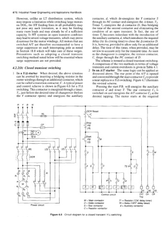
can be called a transition contactor, C. A typical power the revised scheme.
and control scheme is shown in Figure 4.6 for a YfA Pressing the start P.B. will energize the auxiliary
switching. This contactor is energized through a timer, contactor d and timer T. The star contactor C, is
TI, just before the desired time of changeover (before switched on and energizes the AIT contactor C2 at the
the Y contactor opens) and energizes the auxiliary desired tapping. The motor starts at the required
-
1
OCR Reset
1'" I
Control circuit I
Trip
M = Main contactor T1 = Resistor ('ON delay timer)
D = Delta contactor R = Delta ('OFF' delay timer)
Power circuit S = Star contactor d = Auxiliary contactor
C = Resistor contactor
Figure 4.6 Circuit diagram for a closed transient Y/A switching