
Page 96 - Industrial Power Engineering and Applications Handbook
P. 96
Starting of squirrel cage induction motors 4/77
Table 4.1 Comparison between an open and a closed transient switching in terms of voltage and current
Serial no. Condition Open transient Closed transient
._ _-_____
1 Voltage transient across the Up to 3 to 5 p.u. i.e. 3 to 5 (+) There is no voltage transient. The voltage
motor windings across the motor windings remain at ‘V;
or 2.45 to 4.1Vr Section 17.7.2
2 Current overshoot during The current curve becomes a b c d The current curve becomes ah,h,h,c,d
changeover from Y to A, (Figure 4.5) and current overshoots (Figure 4.5). There is no current overshoot
point, a, on Y current curve from oa to ob momentarily, which beyond the normal current in A
(Figure 4.5) may exceed 14-201,
_. __ _. .- . .-
~
Note Since the surge impedance of a circuit is normally very high, as noted in Section 17.8, it is the voltage transient that is the cause of
concern in the above case than the current transient.
I ’
I
fi-3L
1
h3
~@ Control circuit c f
Trip
Power circuit
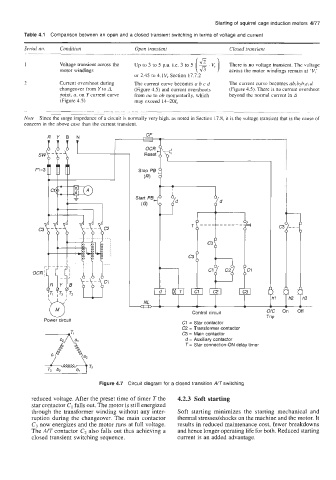
c1 = Star contactor
C2 = Transformer contactor
C3 = Main contactor
d = Auxiliary contactor
T = Star connection-ON delay timer
Figure 4.7 Circuit diagram for a closed transition ATswitching
reduced voltage. After the preset time of timer T the 4.2.3 Soft starting
star contactor C1 falls out. The motor is still energized
through the transformer winding without any inter- Soft starting minimizes the starting mechanical and
ruption during the changeover. The main contactor thermal stressedshocks on the machine and the motor. It
C, now energizes and the motor runs at full voltage. results in reduced maintenance cost, fewer breakdowns
The AIT contactor C2 also falls out thus achieving a and hence longer operating life for both. Reduced starting
closed transient switching sequence. current is an added advantage.