
Page 191 - Industrial Power Engineering and Applications Handbook
P. 191
Special-purpose motors 7/171
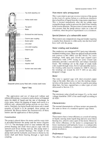
Top shaft adjusting nut Non-return valve arrangement
This is provided to prevent reverse rotation of the pump
in the event of a power failure or a deliberate shutdown
Hollow shaft motor due to backflow of liquid from the rising mains (pipelines).
I
This is located immediately after the last pump stage
casing/discharge outlet to prevent the shaft from rotating
in the reverse direction. The provision of a non-return valve
also ensures that the pump always starts in a shut-off
condition, when the power requirement is at a minimum.
Enclosed line shaft bearing
Special features of a submersible motor
Column pipe coupling These motors are comparatively long and slender requiring
Guide spider a smaller bore diameter to slide easily into the bore hole/
bore well with the pump.
Line shaft
Line shaft coupling
Stator winding and insulation
Column pipe
The conductors are waterproof PVC (polyvinyl chloride)-
insulated winding wires. These are sprayed with polyamide
and conform to IEC 60851 and IEC 60182. For stator
windings, both open and closed type (tunnel type)
Bowls laminations with a PVC lining are used. Closed type
Impellers
laminates provide a smooth bore and reduce frictional
impeller shaft losses. The windings are in the shape of ready-made
coils or pull-through wires. For LT sub-mersible motors,
the winding cable must be suitable for 1000 V, whereas
Suction case sand collar
the windings are wound for 415 V +6% or any other
designed voltage.
Rotor
The rotor is squirrel cage with short-circuited copper
rings at the ends. Here also, to vary the starting charac-
teristics of the motor, the skin effect is used by providing
Deepwell turbine pump fitted with a hollow shaft motor
deep bars, flat bars, tapered bars or other types of slots
(discussed in Section 2.3).
Figure 7.3(a)
Torque
The minimum value of pull-out torque (Tpo) at the rated
The application and use of deep-well turbine and voltage should be 150% of the rated torque according to
submersible pumps, is extensive and a choice will depend IS 9283.
upon the depth of liquid and the rate of discharge. In
rocky areas, where the digging of larger well cavity is a Characteristics
difficult task, submersible pumps provide an easy alter-
native. Similarly, for higher heads and where only a small The normal characteristics of these motors are generally
quantity of liquid is to be pumped, these pumps are the same as those of a standard squirrel cage motor.
preferred. We discuss below the characteristics of these
motors and the application of these pumps. EfJiciency
Construction These motors have a lower efficiency as a result of running
in liquid, causing more liquid drag and also axial thrust
The pump is placed above the motor and the water inlet bearing loss, which is also a part of the motor. However,
is provided between the pump and the motor (Figures this lower efficiency of the motor is compensated by
7.5-7.7). The discharge cover or case contains the top fewer mechanical and hydraulic losses in a submersible
journal bearing and small thrust pad to cope with the motor-pump installation, compared to a vertical turbine
upward axial thrust during start-up. The pump shaft is pump installation.
supported in the journal bearings. The weight of the
pump shaft and the hydraulic axial thrust is borne by the Performance
motor shaft and thrust bearing through a rigid mesh
coupling. The effect of frequency, voltage variation and ambient