
Page 204 - Industrial Power Engineering and Applications Handbook
P. 204
7/184 Industrial Power Engineering and Applications Handbook
may cause a damage to life and property. Such a provision falls phase apart by 180’. This voltage may cause a
is normally desirable for HT motors, where such incidents flashover inside the terminal box if the motor terminals
are more likely due to a higher short circuit level. For a are not adequately spaced, and damage the inter-turn
terminal box with a less stringent design and adequate insulation and the overhangs of the motor windings etc.
air and creepage distances between phases and phase To withstand such overvoltages that may result in higher
and ground, capable of withstanding system faults, phase dielectric and electrodynamic stresses the overhangs can
segregation may not be necessary. An explosion diaphragm be treated by an additional coat of varnish, and a tight
will, however, be essential at a suitable location on the binding. A similar treatment is desirable for the slot coils,
terminal box to allow the high-pressure gases to escape as well as liberal spacings and creepage distances between
in the event of a fault inside the terminal box. the phases and the ground inside the terminal box. In
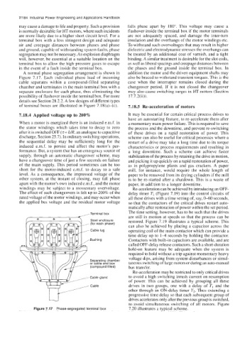
A normal phase segregation arrangement is shown in addition the motor and the driven equipment shafts may
Figure 7.17. Each individual phase lead of incoming also be braced to withstand transient torques. This is the
cable separates within a compound-filled separating case when the interrupter remains closed during the
chamber and terminates in the main terminal box with a changeover period. If it is not closed the changeover
separate enclosure for each phase, thus eliminating the may also cause switching surges in HT motors (Section
possibility of flashover inside the terminal box. For more 17.7.2(ii)).
details see Section 28.2.2. A few designs of different types
of terminal boxes are illustrated in Figure 7.18(a)-(c). 7.18.5 Re-acceleration of motors
7.18.4 Applied voltage up to 200% It may be essential for certain critical process drives to
have an autostarting feature, to re-accelerate them after
When a motor is energized there is an induced e.m.f. in a momentary main power failure. This is required to save
the stator windings which takes time to decay to zero the process and the downtime, and prevent re-switching
after it is switched OFF (z= LIR, an analogue to capacitive of these drives on a rapid restoration of power. This
discharge, Section 25.7). In ordinary switching operations, scheme can also be useful for critical processes where a
the sequential delay may be sufficiently long for the restart of a drive may take a long time due to its torque
induced e.m.f. to persist and affect the motor’s per- characteristics or process requirements and resulting in
formance. But, a system that has an emergency source of a long downtime. Such a scheme can achieve faster
supply, through an automatic changeover scheme, may stabilization of the process by retaining the drive in motion,
have a changeover time of just a few seconds on failure and picking it up quickly on a rapid restoration of power,
of the main supply. This period sometimes can be too as in polypropylene plants and gas crackers. A paper
short for thc motor-induced e.m.f. to decay to a safe mill, for instance, would require the whole length of
level. As a consequence, the impressed voltage of the paper to be removed from its drying cylinders if the mill
other system, at the instant of closing, may fall phase is to be re-started after a shutdown. This is a waste of
apart with the motor’s own induced e.m.f., and the motor paper, in addition to a longer downtime.
windings may be subject to a momentary overvoltage. Re-acceleration can be achieved by introducing an OFF-
The effect of such changeovers is felt up to 200% of the delay timer T, (Figure 7.19) into the control circuits of
rated voltage of the motor windings, and may occur when all these drives with a time setting of, say, 040 seconds,
the applied bus voltage and the residual motor voltage so that the contactors of the critical drives restart auto-
matically after restoration of power within the set period.
Terminal box The time setting, however, has to be such that the drives
are still in motion at speeds so that the process can be
Steel enclosure restored. Figure 7.19 illustrates a typical scheme. This
each
(for
, phase)
can also be achieved by placing a capacitor across the
Cable lug operating coil of the main contactor which can provide a
time delay up to 14 seconds by holding the contactor.
Bushing Contactors with built-in capacitors are available, and are
called OFF-delay release contactors. Such a short-duration
hold-on feature may be adequate when the system is
required to hold without a trip against momentary heavy
voltage dips, arising from system disturbances or simul-
Separating chamber
or cable end box taneous switching of large motors or during an auto-manual
(compound filled) bus transfer.
Re-acceleration may be restricted to only critical drives
to avoid a high switching inrush current on resumption
of power. This can be achieved by grouping all these
drives in two groups, one with a delay of TI and the
other through an ON-delay timer T2. Thus extending a
progressive time delay so that each subsequent group of
drives accelerates only after the previous group is switched,
to avoid simultaneous switching of all motors. Figure
Figure 7.17 Phase-segregated terminal box 7.20 illustrates a typical scheme.