
Page 200 - Industrial Power Engineering and Applications Handbook
P. 200
711 80 Industrial Power Engineering and Applications Handbook
7.12 Specification of motors for rendered incapable of igniting the surrounding hazardous
Zone 0 locations atmosphere. This is achieved by providing joints with
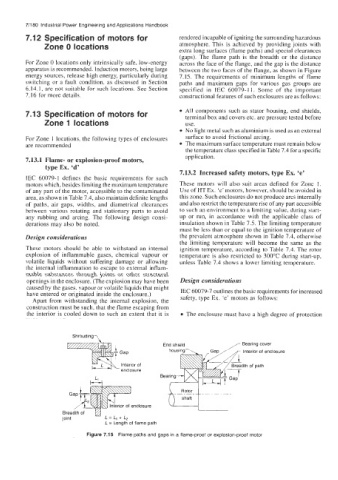
extra long surfaces (flame paths) and special clearances
(gaps). The flame path is the breadth or the distance
For Zone 0 locations only intrinsically safe, low-energy across the face of the flange, and the gap is the distance
apparatus is recommended. Induction motors, being large between the two faces of the flange, as shown in Figure
energy sources, release high energy, particularly during 7.15. The requirements of minimum lengths of flame
switching or a fault condition, as discussed in Section paths and maximum gaps for various gas groups are
6.14.1, are not suitable for such locations. See Section specified in IEC 60079-1 1. Some of the important
7.16 for more details. constructional features of such enclosures are as follows:
7.13 Specification of motors for All components such as stator housing, end shields,
terminal box and covers etc. are pressure tested before
Zone 1 locations use.
No light metal such as aluminium is used as an external
For Zone 1 locations, the following types of enclosures surface to avoid frictional arcing.
are recommended The maximum surface temperature must remain below
the temperature class specified in Table 7.4 for a specific
application.
7.13.1 Flame- or explosion-proof motors,
type Ex. ‘d’
7.13.2 Increased safety motors, type Ex. ‘e’
IEC 60079-1 defines the basic requirements for such
motors which, besides limiting the maximum temperature These motors will also suit areas defined for Zone 1.
of any part of the motor, accessible to the contaminated Use of HT Ex. ‘e’ motors, however, should be avoided in
area, as shown in Table 7.4, also maintain definite lengths this zone. Such enclosures do not produce arcs internally
of paths, air gaps, widths, and diametrical clearances and also restrict the temperature rise of any part accessible
between various rotating and stationary parts to avoid to such an environment to a limiting value, during start-
any rubbing and arcing. The following design consi- up or run, in accordance with the applicable class of
derations may also be noted. insulation shown in Table 7.5. The limiting temperature
must be less than or equal to the ignition temperature of
Design considerations the prevalent atmosphere shown in Table 7.4, otherwise
the limiting temperature will become the same as the
These motors should be able to withstand an internal ignition temperature, according to Table 7.4. The rotor
explosion of inflammable gases, chemical vapour or temperature is also restricted to 300°C during start-up,
volatile liquids without suffering damage or allowing unless Table 7.4 shows a lower limiting temperature.
the internal inflammation to escape to external inflam-
mable substances through joints or other structural
openings in the enclosure. (The explosion may have been Design considerations
caused by the gases. vapour or volatile liquids that might
have entered or originated inside the enclosure.) IEC 60079-7 outlines the basic requirements for increased
Apart from withstanding the internal explosion, the safety, type Ex. ‘e’ motors as follows:
construction must be such, that the flame escaping from
the interior is cooled down to such an extent that it is The enclosure must have a high degree of protection
Shrouding?
aring cover
erior of enclosure
of path
L
erior of enclosure
L = Length of flame path
Figure 7.15 Flame paths and gaps in a flame-proof or explosion-proof motor