
Page 201 - Industrial Power Engineering and Applications Handbook
P. 201
Special-purpose motors 7/181
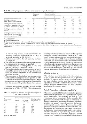
Table 7.5 Limiting temperature and limiting temperature rise for type Ex. 'e' motors
Measuring Class of insulation
method
A E B F H
Limiting temperature R 90' 105" 110" 1 30a 155a
under rated service conditions ("C) T 80 95 100 115 135
Limiting temperature rise under ("C) R 50 65 70 90 115
rated service condition (referred to T 40 55 60 75 95
an ambient temperature of 4OOC)
Limiting temperature at the end of ("C) R 160 175 185 210 235
time tk
Limiting temperature rise at the ("C) R 120 135 145 170 195
end of time t," (referred to an
ambient temperature of 40°C)
As in IEC 60079-7
R - by resistance method.
T - by thermometer method (only permissible if the resistance method is not practicable).
a These values are restricted by 10°C, compared to the working temperature prescribed for standard motors, as in Table 9.1.
These values are composed of the temperature (or the temperature rise) of the windings in rated service and the increase of temperature
during time tE.
to prevent entry of dust, water or moisture. The limiting surface temperatures of motors for these ignition
minimum protection specified is IP:54 (IP:55 is categories in terms of temperature classes TI to T6. The
preferred) according to IEC 60034-5. motor's surface temperature must not exceed the limiting
All terminals must be the anti-loosening and anti- temperature specified in Table 7.6 under the same condition
rotating types. and time tE. The protective switch will thus be set to operate
The minimum clearance and creepage distances must within the heating-up time tE for the relevant temperature
be maintained for conductors as specified. class. Embedded temperature detectors or thermistors are
The temperature rise of windings must be 10°C lower recommended to give the required signal to the tripping
than that specified for normal machines. circuit during an emergency. Figure 7.16 illustrates the
The mechanical clearance between rotating parts, e.g., general requirements for an increased safety motor.
fan and fan cover or the radial air gap between the
stator and the rotor, should not be less than specified Heating-up time tE
to prevent sparking.
The temperature of the windings and other parts must This is the time taken by the stator or the rotor, whichever
not exceed the limiting temperature specified in Table is less, to reach the limiting temperature rise, as specified
7.5, even if the motor, after a prolonged operating period, in Table 7.5, when the starting current Zst is passed through
remains energized in a stalled condition, for a specified the stator windings after the motor has reached thermal
time of tE seconds while tE will not be less than 5 seconds. equilibrium, under rated conditions. For increased safety
motors, this time should not be less than 5 seconds
All gases are classified according to their ignition (preferably 10 seconds or more).
temperatures as in Table 7.4. Table 7.6 recommends the
7.13.3 Pressurized enclosures, type Ex. 'p'
Table 7.6 Temperature class and limiting surface temperature These may be standard TEFC motors suitable for operating
with regard to gas ignition under an internal pressure of 0.05 kP, or a pressure slightly
above atmospheric. The minimum specified is 5 mm
Ignition temperature ("C) water-gauge above atmosphere. During operation this
Temperature Limiting surface pressure is maintained with inert gas or air through an
class Above UP to and temperature, ( T)
including external closed circuit, preventing inflammable gases from
reaching the motor's inner components. Before re-
T6 85 100 85 switching such a motor after a shutdown, inflammable
T5 100 135 100 gases which may have entered the enclosure must first
T4 135 200 135 be expelled. For pressurizing, two holes are normally
T3 200 300 200 drilled on the motor's end shields, one for entry and the
T2 300 450 300 other for exit of the air or gas. For large motors, a totally
T1 450 - 450
enclosed dual-circuit type enclosure is normally used so
As in IEC 60079-14 that the motor's interior is pressurized with air or nitrogen