
Page 25 - Industrial Power Engineering and Applications Handbook
P. 25
1/6 industrial Power Engineering and Applications Handbook
where
4 = &, sin ut
and Q,,, = maximum field strength
In a 3-4 winding, therefore, for the same amount of current,
the torque developed is 50% more than in a 2-4 winding.
The rotor power P developed by torque Tat a speed N
can be expressed by
p=- T.N
974
where
P = rotor power in kW
7' = torque in mkg
N = speed in r.p.m.
Since the kW developed by a 3-4 winding is 50% more s= 1 -
Speed +
than by a 2-4 winding for the same value of stator current Shp
I,, the economics of this principle is employed in an
induction motor for general and industrial use. As standard (a) Typical for an LT motor
practice, therefore, in a multi-phase system, only 3-4
induction motors are manufactured and employed, except
for household appliances and applications, where mostly
single-phase motors are used.
The magnetic field rotates at a synchronous speed, so
it should also rotate the rotor. But this is not so in an
induction motor. During start-up, the rate of cutting of
flux is the maximum and so is the induced e.m.f. in the
rotor circuit. It diminishes with motor speed due to the
reduced relative speed between the rotor and the stator
flux. At a synchronous speed, there is no linkage of flux
and thus no induced e.m.f. in the rotor circuit, consequently
the torque developed is zero.
Since,
(1.3)
4 '
the impedance considered represents only the rotor side. s- 1 N,s = 0
Speed --c
For simplicity, the stator impedance has been ignored, + Slip
being too small with little error.
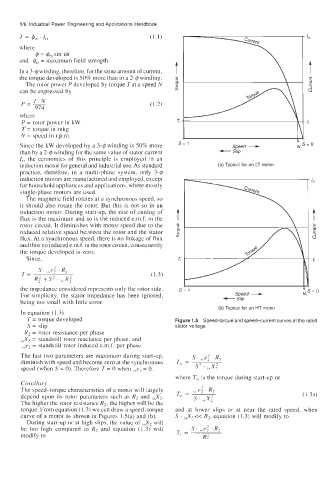
(b) Typical for an HT motor
In equation ( 1.3)
T = torque developed Figure 1.5 Speed-torque and speed-current curves at the rated
S = slip stator voltage
R2 = rotor resistance per phase
\\X2 = standstill rotor reactance per phase, and
,,e2 = standstill rotor induced e.m.f. per phase
The last two parameters are maximum during start-up, S. ,,e: . R2
diminish with speed and become zero at the synchronous T\, Dc s? , ,\X;
speed (when S = 0). Therefore T = 0 when ,\ez = 0.
where T,, is the torque during start-up or
Corollary
The speed-torque characteristics of a motor will largely
depend upon its rotor parameters such as R2 and \\X2. (1.3a)
The higher the rotor resistance R2, the higher will be the
torque. From equation (1.3) we can draw a speed-torque and at lower slips or at near the rated speed, when
curve of a motor as shown in Figures 1 .5(a) and (b). S . ,,X? << R2, equation (1.3) will modify to
During start-up or at high slips, the value of ,,X2 will
be too high compared to R2 and equation (1.3) will
modify to