
Page 29 - Industrial Power Engineering and Applications Handbook
P. 29
1/10 Industrial Power Engineering and Applications Handbook
very high derating and the highly unstable per-formance Table 1.4 Combined permissible voltage and frequency
of the motor. variations
The system may be regarded as balanced when the
negative sequence component does not exceed 1% of the
positive sequence component over a long period, or 1.5% Voltage +5% to -5% to +IO% to -10% to
for short durations of a few minutes and the zero sequence variation -3%
component does not exceed 1% of the positive sequence :: I ;i rz
component. Refer to Section 12.2(v) for more details on Frequency 1 1: -28 -5 %
variation
positive, negative and zero sequence corn-ponents.
According to IEC 60034- 1
System harmonics Nore IS 325 specifies voltage variation f 6% and frequency
A supply system would normally contain certain harmonic variation k 3% or any combination of these.
quantities, as discussed in Section 23.5.2. The influence
of such quantities on an induction motor is also discussed Chapter 7 for special design considerations for certain
in Chapter 23. To maintain a near-sinusoidal voltage types of load requirements.
waveform, it is essential that the harmonic voltage factor
(HVF) of the supply voltage be contained within 0.02 A Effect of voltage variation
for all 1-4 and 3-4 motors, other than design N* motors
and within 0.03 for design N motors, where Voltage variation may influence the motor's performance
HVF= V'T c- (1.11) as shown below.
(i) Torque
Here From equation (1.3), T = ,,e;, and since the standstill
uh = per unit summated value of all the harmonic voltages rotor voltage is a function of supply voltage V,
in terms of the rated voltage V,
n = harmonic order not divisible by 3 (presuming that :. T = VI2
the star-connected motors (normally HT motors) During start-up, at lower voltages, the starting torque is
have only isolated neutrals) in 3-41 motors, i.e. 5, 7,
11 and 13, etc. Beyond 13, the content of harmonic
quantity may be too insignificant to be considered.
For example, for a system having uh5 = 5% Voltage V,
uh7 = 3%
Uhll = 2% and (Vr + 3%, f- 2%)
uh13 = 1%
(V, + 5%, f - 5%)
Then
112
+-
HVF = (7
13
0.026
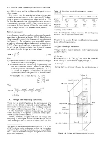
1.6.2 Voltage and frequency variations
These have a great influence on the performance of a Frequency fr 2 1.03
motor and the driven equipment, as analysed later. The -
motors are, however, designed for a combined variation Rated
~
in voltage and frequency according to zone A of Figure parameter!
1.6. The maximum variation during service must fall
within this zone. It will permit a variation in these para- (V, - 3%, f + 2%) -
meters as indicated in Table 1.4.
Where, however, a higher variation in voltage and
frequency is envisaged, motors suitable to fall within
zone B in Figure 1.6 can also be manufactured. See also t
(Vr-7%, f+3%-
*IEC 60034- 12 has recommended four rotor designs, i.e. N, Hand
NY, HY, to define starting performance for DOL and Y/A startings
respectively. They are along similar lines, ones to those in NEMA
MG- 1. They define minimum torques, though the manufacturer
can produce better ones. Figure 1.6 Voltage and frequency limits for motors