
Page 30 - Industrial Power Engineering and Applications Handbook
P. 30
Theory, performance and constructional features of induction motors 1/11
reduced squarely and one should ensure that this is 123 I
sufficient to accelerate the load within a reasonable time,
without injurious heat or causing a stalled condition.
This aspect is discussed at length in Chapter 2. The torque
however. improves in the same proportion at higher
voltages.
Example 1.2
During a run, if the supply voltage to a motor terminal drops
to 85% of its rated value, then the full load torque of the
motor will decrease to 72.25%. Since the load and its torque
requirement will remain the same, the motor will start to drop
speed until the torque available on its speed-torque curve
has a value as high as 100/0.7225 or 138.4% of T,, to sustain
this situation. The motor will now operate at a higher slip,
increasing the rotor slip losses also in the same proportion.
See equation (1.9) and Figure 1.7.
Corollary
Speed + s4 s3 s2
To ensure that the motor does not stall or lock-up during
pick-up under such a condition, it should have an Figure 1.8 Significance of lower Tpo slip
adequately high pull-out torque (TJ.
Since the motor now operates at a higher slip, the slip
losses as well as the stator losses will increase. A circle dielectric stresses and may deteriorate, influencing its
diagram (Figure 1.16) illustrates this.
Judicious electrical design will ensure a pull-out torque operating life, while at overvoltages of about 10% and
slip as close to the full-load slip as possible and minimize higher the insulation may even fail. Moreover. the stator
the additional slip losses in such a condition. See Figure current may start to rise much more than the corresponding
1.8. A motor with a pull-out torque as close to full load slip increase in the output to account for higher no-load losses
as possible would also be able to meet a momentarily and a poorer power factor. Figure 1.9 illustrates the
enhanced load torque during a contingency without any approximate effect of voltage variation on the motor
injurious heat or a stalling condition. output. Higher voltages beyond 5% may thus be more
harmful, even if the insulation level is suitable for such
An increased voltage should improve the performance voltages. The circle diagram of Figure 1.16 explains this
of the machine in the same way by reducing slip and the by shifting the semicircle to the right, because of higher
associated slip losses and also stator losses as a result of In( and and a larger circle diameter, due to higher I,,
lower stator currents, but this would hold good only up
to a certain increase in voltage, say up to 5%. Beyond
this, not only will the no-load losses, as discussed above,
assume a much higher proportion than the corresponding
reduction in the stator current and the associated losses,
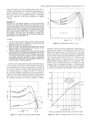
the winding insulation will also be subject to higher 120
112 5
107 5
TPO t I1O
s 100
,4
t2 -0
-
0
F 90
.+.
8
80
70 0
95 105
s= 1 Speed- sz SI % Apphed voltage +
+ Slip s2 ' SI * Motors are designed to develop rated output at 95% voltage
Figure 1.7 Higher full-load slip at lower voltages Figure 1.9 Effect of voltage variation on the motor output