
Page 27 - Industrial Power Engineering and Applications Handbook
P. 27
1/8 Industrial Power Engineering and Applications Handbook
1.2.2 Rotor current 1.4 Motor ratings and frame sizes
With the same parameters, the rotor current of a motor,
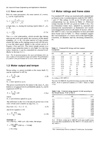
Zrr, can be expressed by The standard kW ratings are internationally adopted and
are based on the recommendations made by IEC 60072-
1 and 2.* The ratings in kW up to 110 kW and their
I, = s ' sse2 (1.7) corresponding h.p. are shown in Table 1.1. Preferred
JR; + S2 . ,,X;
ratings beyond 110 kW are given in Table l.l(a). For
at high slips, i.e. during the starting region when S . ,,X2 recommended frame sizes, adopted by national and
>> RZ: international manufacturers to harmonize and ensure
interchangeability between all makes of motors, refer to
(1.7a) IEC 60072-1 and 2. For easy reference we have provided
these frame sizes in Table 1.2. These standards suggest
the vital dimensions of a motor such as the shaft height,
This is a vital relationship, which reveals that during extension, its diameter and the mounting dimensions,
start-up and until such speed, the reactance of the motor
windings ,,X2 >> R2, the rotor current will also remain etc.
almost the same as the starting current and will fall only
at near the rated speed. (Refer to the current curves in
Figures 1.5(a) and (b)). The initial inrush current in a
squirrel cage induction motor is very high. In a slip-ring Table 1.1 Preferred kW ratings and their nearest
motor, however, it can be controlled to a desired level. horsepower
(Refer to Section 5.2.1.)
kW HP kW HP kW HP
Note For all practical purposes the stator performance data are
only a replica of rotor data for torque and current. The performance 0.06 0.08 2.2 3.0 31 50
of a motor is the performance of its rotor circuit and its design. 0.09 0.12 3.7 5.0 45 60
0.12 0.16 5.5 7.5 55 15
0.18 0.25 7.5 10.0 75 100
1.3 Motor output and torque 0.25 0.33 9.3 12.5 90 125
0.31 0.50 11 15 110 150"
0.55 0.75 15 20 -
Motor rating, i.e. power available at the motor shaft, P,, 0.75 I .o 18.5 25 -
can be expressed in kW by 1.1 1.5 22 30 -
1.5 2.0 30 40 -
According to IEC 60072-1
where
N, = rotor speed in r.p.m. aBeyond 1104000 kW, the preferred ratings can follow the 'Renard
Series', R-20 of preferred numbers as in IS0 3. Refer to Table
The power transferred by the stator to the rotor, P,, also l.l(a).
known as air gap power at synchronous speed, N,, can be
expressed in kW by:
Table l.l(a) Preferred ratings beyond 110 kW according to
(1.8a) the Renard Series, 'R-20' of IS0 3
where kW kW kW
N, = synchronous speed in r.p.m.
112 400 1400
The difference in the two is the electric power loss in the 125 450 1600
rotor circuit and is known as slip loss, i.e. 140 500 1800
160 560 2000
Slip loss = P, - P, = S . P, (1.9) 180 630 2240
200 710 2500
and from equation (I .8) 224 800 2800
250 900 3150
280 1000 3550
(1.10)
315 1120 4000
355 1250
Example 1.1 Note Of these, ratings up to 1000 kW with some modifications
For a 150 h.p., 1480 r.p.m. (N,) motor, the torque have now been standardized by IEC 60072-1. For details refer to
IEC 60072- 1.
T, = '10x974(15~h.p. = 1lOkW)
1480
= 72.5 mkg *IEC: International Electro-technical Commission, Switzerland.