
Page 31 - Industrial Power Engineering and Applications Handbook
P. 31
1/12 Industrial Power Engineering and Applications Handbook
thereby increasing I, a proportion of which will depend by the lower voltage, the stator must draw a higher current
upon the magnitude of voltage. from the supply to compensate for the higher losses at
lower voltages. Since
Important note on starting torque, T,,
It is important to note that at voltages lower than rated
the degree of saturation of the magnetic field is affected
as in equations (1.1) and (1.5). There will also be a further if the supply voltage falls to 85%, the stator current for
drop in the supply voltage at the time of start-up. The net the same load should increase by
effect of such factors is to further influence the starting I: = IJ0.85,i.e. by roughly 18% and if the voltage
performance of the motor. See also IEC 60034-12. For increases by 15%, the stator current should decrease to
risk-free duties and large motors, HT motors particularly, IJl.15 or 87% of Ir, i.e. areduction of 13%. These would
which have a comparatively lower starting torque, it would be the values when the core losses are ignored. But the
be appropriate to allow margins for such factors during core losses will also vary with the voltage as discussed
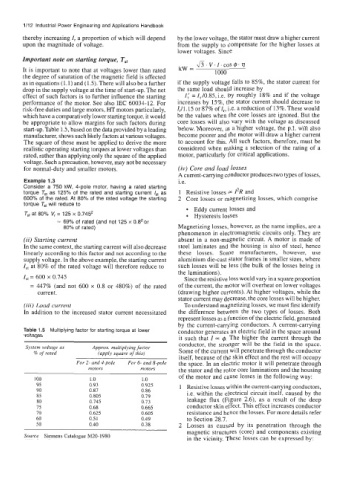
start-up. Table 1 .5, based on the data provided by a leading below. Moreover, at a higher voltage, the p.f. will also
manufacturer, shows such likely factors at various voltages. become poorer and the motor will draw a higher current
The square of these must be applied to derive the more to account for this. All such factors, therefore, must be
realistic operating starting torques at lower voltages than considered when making a selection of the rating of a
rated, rather than applying only the square of the applied motor, particularly for critical applications.
voltage. Such a precaution, however, may not be necessary
for normal-duty and smaller motors. (iv) Core and load losses
A current-canying conductor produces two types of losses,
Example 1.3 i.e.
Consider a 750 kW, 4-pole motor, having a rated starting
torque Td as 125% of the rated and starting current /* as 1 Resistive losses = 12R and
600% of the rated. At 80% of the rated voltage the starting 2 Core losses or magnetizing losses, which comprise
torque T. will reduce to
Eddy current losses and
Tst at 80% V, = 125 x 0.745' Hysteresis losses
= 69% of rated (and not 125 x 0.82 or
80% of rated) Magnetizing losses, however, as the name implies, are a
phenomenon in electromagnetic circuits only. They are
(ii) Starting current absent in a non-magnetic circuit. A motor is made of
In the same context, the starting current will also decrease steel laminates and the housing is also of steel, hence
linearly according to this factor and not according to the these losses. Some manufacturers, however, use
supply voltage. In the above example, the starting current aluminium die-cast stator frames in smaller sizes, where
Ist at 80% of the rated voltage will therefore reduce to such losses will be less (the bulk of the losses being in
the laminations),
ISt = 600 x 0.745 Since the resistive loss would vary in a square proportion
= 447% (and not 600 x 0.8 or 480%) of the rated of the current, the motor will overheat on lower voltages
current. (drawing higher currents). At higher voltages, while the
stator current may decrease, the core losses will be higher.
(iii) Loud current To understand magnetizing losses, we must first identify
In addition to the increased stator current necessitated the difference between the two types of losses. Both
represent losses as a function of the electric field, generated
by the current-carrying conductors. A current-carrying
Table 1.5 Multiplying factor for starting torque at lower conductor generates an electric field in the space around
voltages it such that I= 4. The higher the current through the
conductor, the stronger will be the field in the space.
System voltage as Approx. multiplying factor Some of the current will penetrate through the conductor
% of rated (apply square of this)
itself, because of the skin effect and the rest will occupy
For 2- and 4-pole For 6- and &pole the space. In an electric motor it will penetrate through
motors motors the stator and the rotor core laminations and the housing -
IO0 1 .o 1 .O of the motor and cause losses in the following way:
95 0.93 0.925 1 Resistive losses within the current-carrying conductors,
90 0.87 0.86 i.e. within the electrical circuit itself, caused by the
85 0.805 0.79
80 0.745 0.73 leakage flux (Figure 2.6), as a result of the deep
75 0.68 0.665 conductor skin effect. This effect increases conductor
70 0.625 0.605 resistance and hence the losses. For more details refer
60 0.5 1 0.49 to Section 28.7.
50 0.40 0.38 2 Losses as caused by its penetration through the
magnetic structures (core) and components existing
Source Siemens Catalogue M20-1980 in the vicinity. These losses can be expressed by: