
Page 26 - Industrial Power Engineering and Applications Handbook
P. 26
Theory, performance and constructional features of induction motors 1/7
or
(1.3b)
where synchronous speed
7', is referred to as the rated torque.
120.f
R? and ,,X, are thus the vital parameters that are used N, = - (I .6a)
r.p.m
at the design stage to accomplish the desired characteristics P
and performance of an induction motor. The normal f= frequency of the supply system in Hz and
starting torque T,, for a medium-sized LT squirrel cage
motor, say up to 400 kW, can be attained up to 200- p = number of poles in the stator winding.
250% and even more of the full-load torque T,, and the
pull-out torque Tp up to 200-350% of T, (see also Chapter 1.2.1 Stator current
2). In slip ring motors, the starting torque (TJ can be An induction motor draws a very high current during
varied up to its pull-out torque (Tpo). (See Chapter 5.) start-up as a result of magnetic saturation (Section
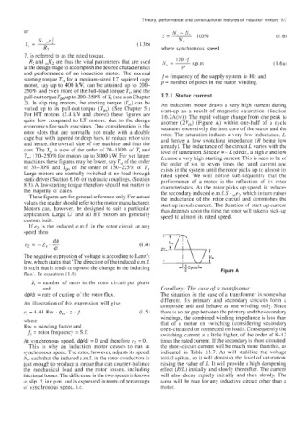
For HT motors (2.4 kV and above) these figures are 1.6.2A(iv)). The rapid voltage change from one peak to
quite low compared to LT motors, due to the design another (2Vm) (Figure A) within one-half of a cycle
economics for such machines. One consideration is the saturates excessively the iron core of the stator and the
rotor slots that are normally not made with a double rotor. The saturation induces a very low inductance, L,
cage hut with tapered or deep bars, to reduce rotor size and hence a low switching impedance (R being low
and hence, the overall size of the machine and thus the already). The inductance of the circuit L varies with the
cost. The T,, is now of the order of 70-130% of T, and level of saturation. Since e = - L (dildt), a high e and low
Tpo 170-250% for motors up to 3000 kW. For yet larger L cause a very high starting current. This is seen to be of
machines these figures may be lower, say T,, of the order the order of six to seven times the rated current and
of 33-70% and Tpo of the order of 1.50-225% of T,. exists in the system until the rotor picks up to almost its
Large motors are normally switched at no-load through rated speed. We will notice sub-sequently that the
static drives (Section 6.16) or hydraulic couplings, (Section performance of a motor is the reflection of its rotor
8.3). A low starting torque therefore should not matter in characteristics. As the rotor picks up speed, it reduces
the majority of cases. the secondary induced e.m.f. S. sse2, which in turn raises
These figures are for general reference only. For actual the inductance of the rotor circuit and diminishes the
values the reader should refer to the motor manufacturer. start-up inrush current. The duration of start-up current
Motors can, however, be designed to suit a particular thus depends upon the time the rotor will take to pick-up
application. Large LT and all HT motors are generally speed to almost its rated speed.
custom bui It.
If e? is the induced e.m.f. in the rotor circuit at any
speed then
The negative expression of voltage is according to Lenz's
law. which states that 'The direction of the induced e.m.f.
is such that it tends to oppose the change in the inducing Figure A
flux'. In equation (1.4)
Z, = number of turns in the rotor circuit per phase
and Corolluly: The case ($ u transformer
d$ldt = rate of cutting of the rotor flux. The situation in the case of a transformer is somewhat
different. Its primary and secondary circuits form a
An illustration of this expression will give
composite unit and behave as one winding only. Since
e2 = 4.44 Kw . $", . z, ' f, (1.5) there is no air gap between the primary and the secondary
windings, the combined winding impedance is less than
where that of a motor on switching (considering secondary
Kw = winding factor and open-circuited or connected on load). Consequently the
J; = rotor frequency = S.f. switching current is a little higher, of the order of 8-12
At synchronous speed, dqdt = 0 and therefore e2 = 0. times the rated current. If the secondary is short circuited,
This is why an induction motor ceases to run at the short-circuit current will be much more than this, as
synchronous speed. The rotor, however, adjusts its speed, indicated in Table 13.7. As will stabilize the voltage
N,, such that the induced e.m.f. in the rotor conductors is initial spikes, so it will diminish the level of saturation,
just enough to produce a torque that can counter-balance raising the value of L. It will provide a high dampening
the mechanical load and the rotor losses, including effect (RlL) initially and slowly thereafter. The current
frictional losses. The difference in the two speeds is known will also decay rapidly initially and then slowly. The
as slip, S, in r.p.m. and is expressed in terms of percentage same will be true for any inductive circuit other than a
of synchronous speed, i.e. motor.