
Page 34 - Industrial Power Engineering and Applications Handbook
P. 34
Theory, performance and constructional features of induction motors 1/15
Vf - $,,, .J i.e. for the same applied voltage, V,, an and vice versa. Table 1.6 shows approximate variations
increase or decrease in the system frequency will in these parameters with frequency.
decrease or increase the flux in the same proportion.
Consider the variation in the rotor current I,, with C Effect of ambient temperature
frequency from equation (1.7):
The motors are universally designed for an ambient
S' ,,P?
I,, = ____________ - temperature of 40°C according to IEC 60034- I, unless
I R: + S' ,,Xi specified otherwise. For temperatures below 40"C, the
motor will run cooler by the amount the ambient tem-
since ,,X2 = 27r. f . L perature is lower. To utilize a higher output because of
lower ambient temperature may. however, not be worth-
where while.
L = inductance of the rotor circuit For a higher ambient temperature, the end temperature
of the winding will exceed the permissible limit by the
amount the ambient tempcraturc is higher. For example,
for a class E motor, an ambient temperature of 50°C will
I cause the end temperature to reach 125°C as against
or - -
.f 115°C permissible by the resistance method. For details
rcfcr to Sections 9.1 and 1 1.3.2.
Torque To restrict the end temperature to less than the per-
From equation (I. 1) missible limits, it is essential that the motor output be
reduced, or for a required output, a higher-capacity motor
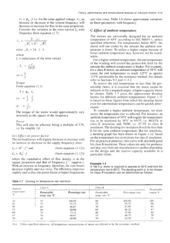
be chosen. Table 1.7 gives the approximate derating
factors for different ambient temperatures. Figure I. 1 I
is based on these figures from which the derating factor
1 even for intermediate temperatures can be quickly deter-
nr - - in i ned .
.f
To consider a higher ambient temperature, we must
The torque of the motor would approximately vary assess the temperature rise so affected. For instance, an
inversely as the square of the frequency.
ambient temperature of 50°C will require the temperature
P0w.er rise to be restricted by 10°C or 65/75, Le. 86.67% in
This will also be affected, being a multiple of T.N, class E insulation and 70/80, Le. 87.5% in class B
i.e. by roughly l/f insulation. The derating for insulation B will be less than
E for the same ambient temperature. But for simplicity,
a derating graph has been drawn in Figure 1.12. based
(iv) Effect on power factor on the temperature rise restrictions for class E insulation.
The no-load losses will slightly decrease or increase with For all practical purposes, this curve will also hold good
an increase or decrease in the supply frequency since for class B insulation. These values are only for guidance
L, H' . .f' and (from equation (I. 12)) and may vary from one manufacturer to another depending
on the design and the reserve capacity available in a
Lh Bt:.f (from equation (I. 13)) particular frame.
where the cumulative effect of flux densit is in the
Y
square proportion and that of frequency f (approx.). Example 1.4
With an increase in frequency, therefore, the core losses A 100 h.p. motor is required to operate at 50°C and limit the
decrease slightly and vice versa. The efficiency improves temperature rise to 60°C. The derating and h.p. to be chosen
slightly and so does the power factor at higher frequencies for class B insulation can be determined as follows:
Table 1.7 Derating for temperature rise restriction
! C'iass E Cluss B Percrnragc. rise Perm issihle
Permissible
orrtpur %
; Pernii,s.sible Percentage rise i temp. rise "C
temp. rise "C
Nore Unless specified otherwise, all temperature measurements of motor arc referred to by the resistance method