
Page 38 - Industrial Power Engineering and Applications Handbook
P. 38
Theory, performance and constructional features of induction motors 111 9
R2 = rotor resistance per phase
Z, = number of turns in the stator circuit per phase
Z, = number of turns in the rotor circuit per phase
5 At load current I,, i.e. OP, the rotor current I,, is AP.
PP, will determine the power input per phase and the
I performance of the motor as follows:
(i) Power input = 3 . V, . PPI watts
(ii) Core and friction loss = 3 . V, . DI D2 watts
(iii) Stator copper loss = 3 Vi . MI Po watts
(iv) Rotor copper loss = 3 . V, . /MI watts
(v) Motor output = 3 . Vt . Ph watts
AB is known as the output line, since the output
is measured above this.
. _ ~ (vi) Running torque,
I,, = /I;, + I, T = 3 . V, . PM, synchronous watts
/A = Loss or active component supplying the hysteresis and eddy
current losses to the stator core. T.N,
I,,, = Magnetizing or reactive component producing the field (flux). and since 3 ' Vt . PMl = ~ 0.974
la = Active or torque producing component.
3 V( '0.974' PMI
Figure 1 .I 5 Simple equivalent circuit diagram of a motor :. T = N, mkg.
Ri = rotor resistance referred to stator This is the maximum torque that can be
S.s,X2 = X; = rotor reactance referred to stator developed by the rotor during a run, but the
useful torque will be in accordance to output,
I,( = no-load current
1.e.
Re' = RS . I-s is the external rotor resistance 3. V, . Pb
S
referred to the stator. '0.974 mkg
N,
All these values are considered on per phase basis. Since the maximum torque is measured by line
AM, it is known as the torque line.
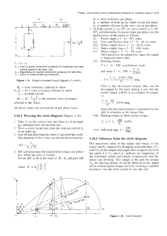
1.10.1 Drawing the circle diagram (Figure 1.16) (vii) Starting torque or short-circuit torque
BM
Take V, on the vertical axis and draw I,( at an angle T,, = 3 . V( ' ~ ' 0.974
$ne obtained from the no-load test. Nr
From a short-circuit test draw the start-up current I,, (viii) Full-load slip, S = -
bM,
at an angle &. PMI
Join AB and determine the centre C and draw the circle.
The diameter of the circle can also be determined by: 1.10.2 Inference from the circle diagram
The maximum value of the output and torque of the
motor can be obtained by dropping perpendiculars CCI
and CC3 on the output and torque lines respectively from
BB' will determine the locked rotor torque and power the centre C.CIC2 and C3C4 indicate the magnitude of
loss while the rotor is locked. the maximum output and torque, respectively, that the
Divide BB' at M in the ratio of R; : RI and join AM motor can develop. This torque is the pull-out torque
where Ki = R2( $)' Tpo In slip-ring motors it can be obtained at any speed
on the normal speed-torque curve by inserting a suitable
resistance into the rotor circuit to vary the slip.
'L
0 I& 9 4 Figure 1.16 Circle diagram