
Page 37 - Industrial Power Engineering and Applications Handbook
P. 37
111 8 Industrial Power Engineering and Applications Handbook
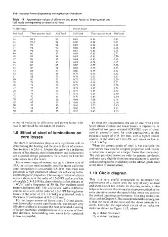
Table 1.9 Approximate values of efficiency and power factor at three-quarter and
half loads corresponding to values at full load
% Efficiency Power factor
Full load Three-quarter loud Half load Full load Three-quurter loud Half load
94 93.5 92 0.9 1 0.89 0.83
93 92.5 91 0.90 0.88 0.8 1
92 92 91 0.89 0.86 0.78
91 91 90 0.88 0.85 0.76
90 91 90 0.87 0.84 0.75
89 90 89 0.86 0.82 0.12
88 89 88 0.85 0.8 I 0.70
87 88 87 0.84 0.80 0.69
86 87 86 0.83 0.79 0.67
85 86 85 0.82 0.77 0.66
84 85 84 0.8 I 0.76 0.65
83 84 83 0.80 0.75 0.64
82 82 81 0.79 0.74 0.62
81 81 19 0.78 0.12 0.61
80 80 I1 0.71 0.70 0.59
79 79 16 0.76 0.69 0.57
78 77 I4 0.75 0.68 0.56
77 76 13 0.74 0.61 0.54
76 75 12 0.73 0.65 0.52
15 74 71 0.72 0.63 0.50
72 70 64 0.70 0.63 0.50
70 67 60 0.68 0.5 8 0.48
65 62 61 0.65 0.56 0.46
60 57 46 0.63 0.55 0.45
55 51 45 0.60 0.5 I 0.42
50 47 35 0.55 0.45 0.35
extent of variation in efficiency and power factor with To meet this requirement, the use of steel with a still
load is universal for all makes of motors. better silicon content and lower losses is imperative. A
cold-rolled non-grain oriented (CRNGO) type of sheet
1.9 Effect of steel of laminations on steel is generally used for such applications, in the
core losses thickness range of 0.35-0.5 mm, with a higher silicon
content of the order of 2.0-1.8% and losses as low as
The steel of laminations plays a very significant role in 1 .O-1 .S W/kg.
determining the heating and the power factor of a motor. When the correct grade of steel is not available the
See Section 1.6.2A(iv). A better design with a judicious core losses may assume a higher proportion and require
choice of flux density, steel of laminations and its thickness a reduction in output or a larger frame than necessary.
are essential design parameters for a motor to limit the The data provided above are only for general guidance,
core losses to a low level. and may vary slightly from one manufacturer to another
For a lower range of motors, say up to a frame size of and according to the availability of the silicon-grade steel
355, the silicon steel normally used for stator and rotor at the time of manufacture.
core laminations is universally 0.5-0.65 mm thick and
possesses a high content of silicon for achieving better 1.10 Circle diagram
electromagnetic properties. The average content of siIicon
in such sheets is of the order of 1.3-0.8% and a core loss This is a very useful nomogram to determine the
of roughly 2.3-3.6 Wkg, determined at a flux density of performance of a motor with the help of only no-load
I Wdm2 and a frequency of 50 Hz. For medium-sized and short-circuit test results. In slip-ring motors, it also
motors, in frames 400-710, silicon steel with a still better helps to determine the external resistance required in the
content of silicon, of the order of 1.3-1.8% having lower rotor circuit to control the speed of the motor and achieve
losses of the order of 2.3-1.8 W/kg is preferred, with a the desired operating performance. Slip-ring motors are
thickness of lamination of 0.5-0.35 mm. discussed in Chapter 5. The concept behind this nomogram
For yet larger motors of frame sizes 710 and above, is that the locus of the rotor and the stator currents is a
core losses play a more significant role, and require very circle. Consider the equivalent circuit of an induction
effective cooling to dissipate the heat generated. Cooling motor as shown in Figure 1.15, where
of larger machines, complicated as it is in view of their
size and bulk, necessitating core losses to be restricted R, = stator resistance
as low as possible. X, = stator reactance