
Page 254 - Industrial Power Engineering and Applications Handbook
P. 254
Installation and maintenance of electric motors 10/233
One can adopt a suitable procedure of installation, Mounting of a bearing or a pulley
grouting, type of foundation and alignment etc., depending Bearings up to medium sizes can be driven on the shaft
upon the size of motor, the duty it has to perform and the seat with the aid of a tubular drift, supported on the inner
location of the installation (such as hazardous or seismic, race of the bearing, then by hammering it gently with a
etc.). Here we discuss briefly only the important aspects mallet, to transmit the blows at the other end to a rigid
of installation and maintenance of electric motors.
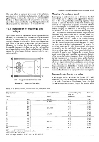
support. For large motors or pulleys, however, a fixture
as shown in Figure 10.1 can be used. The purpose of this
10.1 Installation of bearings and fixture is to grip the inner race of the bearing and cause
pu I ley s no thrust on the balls or the rollers of the bearing. IS0
286-1 recommends the tolerances and fits for pulley bores
and these may be followed for an ideal fit. Table 10.1
Special care needs be taken when mounting or removing gives tolerances in the pulley bore for different shaft
the pulley or the bearing from the motor shaft. Carelessness diameters and Table 10.2 those in the bearing housing
in using a correct procedure or proper tooling may be (end shield) bore diameter, where the bearing’s outer
detrimental to the bearing’s life. It may even damage the race fits, as well as the motor shaft diameter, on which
end shield of the motor at the other end. Any hammer the inner race of the bearing is mounted. The bearing fits
blows on the bearing, directly or indirectly, can cause are thus governed by the dimensional tolerances
irreparable damage to the bearing and the end shield at permissible for the end shield bore diameter and the
the other end of the motor. In view of a bearing’s delicate diameter of the motor shaft. These are called tight fit or
nature, the following methods are recommended to carry shrink fit. It may be seen that any slip between the end
out such tasks.
shield bore and the outer race of the bearing or the diameter
of the motor shaft and the inner race (bore) of the bearing,
during transmission of load, may cause undue heating,
I
vibrations and noise. This may also adversely, influence the
efficiency of power transmission, and cause severe damage
to the bearing inner and outer races, the shaft and the
bearing housing (end shield) due to friction, abrasive wear,
fretting, corrosion and cracks. All these effects must
therefore be eliminated by a proper fit in all mating parts.
Dismounting of a bearing or a pulley
A claw-type puller, as shown in Figure 10.2, with
Note The jig can also be motor operated adjustable jaws must be used when pulling out the bearing
or the pulley from its seat. The claws are so set that they
Figure 10.1 Mounting of the pulley do not bear against the outer ring of the bearing while
Table 10.1 Shaft diameter, its tolerance and pulley bore size
Shaft diameter Tolerance Value of tolerance Tolerance for pulley Bore size
bore
(mm) (mm) (microns) (mm)
9 JS6 LO045 + 15 9.015
11 f .0055 + 18 11.018
14 JS6 + 18 14.018
19 E } + 21 19.021
24 f 0.0065 + 21 24.021
28 JS6 + 21 28.021
38 E } + 25 38.025
42 + 0.018 + 25 42.025
48 K6 + 25 48.025
55 + 30 55.030
60 + 30 60.030
65 + 0.030 + 30 65.030
75 m6 + 30 75.030
80 m6 + 30 80.030
90 m6 + 0.035 + 35 90.035
aThere is no lower limit of tolerance in holes.
1 micron = 0.001 mm (lpm).
Note: For larger sizes refer to IS0 286-1 or IEC 60072-2.