
Page 249 - Industrial Power Engineering and Applications Handbook
P. 249
9/228 Industrial Power Engineering and Applications Handbook
void and the remaining voltage across the insulation
(dielectric). When the applied voltage is increased, the
air of the void at a certain value of the applied voltage
will break down, causing an internal discharge. The void
is now short-circuited and the full voltage will appear
across the insulation (dielectric). The tan 6 - voltage
curve at this point, where ionization begins, shows a
rapid change (Figure 9.8). In practice, an insulation system,
whether of a coil, winding or a slot, will always contain
many small voids, often located at different depths of
the dielectric. The higher the number of voids, the steeper
will be the tan 6V curve beyond a certain voltage level
(Figure 9.8). The value of tan 6 at low voltage and the
rate of change of tan 6, i.e A tan 6, with an increase in
the applied test voltage, gives an indication of the condition
of the dielectric at higher test voltages, and also suggests
the presence of moisture. Hence, A tan 6 is a measure of
voids in the insulation system and indicates the quality
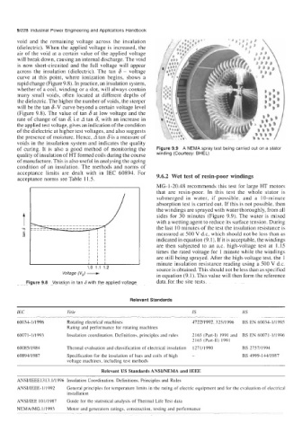
of curing. It is also a good method of monitoring the Figure 9.9 A NEMA spray test being carried out on a stator
quality of insulation of HT formed coils during the course winding (Courtesy: BHEL)
of manufacture. This is also useful in analysing the ageing
condition of an insulation. The methods and norms of
acceptance limits are dealt with in IEC 60894. For 9.6.2 Wet test of resin-poor windings
acceptance norms see Table 1 1.5.
MG- 1-20.48 recommends this test for large HT motors
that are resin-poor. In this test the whole stator is
submerged in water, if possible, and a 10-minute
absorption test is carried out. If this is not possible, then
the windings are sprayed with water thoroughly, from all
sides for 30 minutes (Figure 9.9). The water is mixed
with a wetting agent to reduce its surface tension. During
the last 10 minutes of the test the insulation resistance is
measured at 500 V d.c, which should not be less than as
indicated in equation (9.1). If it is acceptable, the windings
are then subjected to an a.c. high-voltage test at 1.15
times the rated voltage for 1 minute while the windings
Voltage (V,) - minute insulation resistance reading using a 500 V d.c.
are still being sprayed. After the high-voltage test, the 1
source is obtained. This should not be less than as specified
data for the site tests.
Figure 9.8 Variation in tan 6 with the applied voltage in equation (9.1). This value will then form the reference
Relevant Standards
IEC Title IS BS
60034- l/1996 Rotating electrical machines 472211992. 32511996 BS EN 60034-1/1995
Rating and performance for rotating machines
60071-1/1993 Insulation coordination. Definitions, principles and rules 2165 (Part-I) 1991 and BS EN 60071-1/1996
2165 (Part-11) 1991
60085/ 1984 Thermal evaluation and classification of electrical insulation I27 1/1990 BS 2757/1994
60894/1987 Specification for the insulation of bars and coils of high - BS 4999-144/1987
voltage machines, including test methods
Relevant US Standards ANSI/NEMA and IEEE
ANSUIEEE13 13.1/1996 Insulation Coordination. Definitions, Principles and Rules
ANSI/IEEE-I/1992 General principles for temperature limits in the rating of electric equipment and for the evaluation of electrical
installation
ANSIlIEE 101/1987 Guide for the statistical analysis of Thermal Life Test data
NEMA/MG.1/1993 Motor and generators ratings, construction, testing and performance