
Page 248 - Industrial Power Engineering and Applications Handbook
P. 248
Winding insulation and its maintenance 91227
8 Winding connections for insulation resistance test or leakage current within the windings and leads to erosion
It is recommended to test each phase to ground in soft materials, or microscopic cracks in hard ones. All
separately with the other phases also grounded. This this may also lead to an eventual failure of thc insulation.
is because the insulation resistance of a complete The level of such dischargesAeakage currents should
winding to ground does not provide a check of the therefore be restricted as much as possible, so that they
insulation condition between the windings. cause the least harm to the insulation of the windings,
It is observed that the insulation resistance of one during the machine's long years of opcration. For an
phase with the other two phases grounded is illustration of the leakage current circuit. see Figures 9.6
approximately twice that of the entire winding. and 9.7.
Therefore, when the three phases are tested sepa- By measuring the capacitive and leakage currents, the
rately. the observed value of the resistance of each phase angle (loss angle) 6 bctween them can be
phase is divided by two to obtain the actual insulation determined. The tangent of this angle. tan 6, will give an
resistance. indication of the condition of insulation:
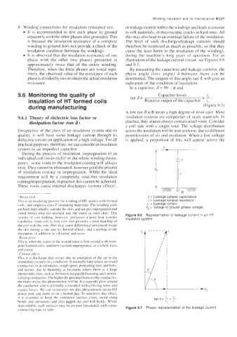
In a capacitor. 6 = 90 - @ and
9.6 Monitoring the quality of ran 6= Capacitor losses - -_
i,
insulation of HT formed coils Reactive output of the capacitor i,
during manufacturing (Figure 9.7)
A low tan 6 will mean a high degree of resin cure. Most
9.6.1 Theory of dielectric loss factor or insulation systems are composites of many materials. In
dissipation factor (tan 6) practice, they almost always contain small voids. Consider
a coil side with a single void. The voltage distribution
Irrespective of the class of an insulation system and its across the insulation will be non-uniform. due to different
quality, it will have some leakage current through its permittivities of air and insulation. When a low voltage
dielectric circuit on application of a high voltage. For all is applied, a proportion of this will appear across the
practical purposes. therefore. we can consider an insulation
system as an imperfect capacitor.
During the process of insulation. impregnation of an
individual coil (resin-rich)* or the whole winding (resin-
poor)..'some voids in the insulation coating will always I Tb
exist. They cannot be elirninated, however good the process
of insulation coating or impregnation. While the ideal
requirement will be a completely void-free insulation
coatinghmpregnation, in practice this cannot be achieved.
These voids caube internal discharges (corona effect)?,
.Ii Res ir / - rich c = Leakage lumped capacitance
Thi\ i\ an insulating process for winding of HT motors with formed r = Leakage lumped resistance
coils. and employs clasi F insulating materials. The winding coils I, = Leakage current
are huilt individually. outside the \lots and are pre-impregnated and Vg = Voltage to ground (phase voltage)
cured before they are inserted into the stator or rotor slots. This Figure 9.6 Representation of leakage current in an HT
term of coil making. however. possesses a poor heat transfer insulation system
ability. troni coil to iron core :ind provides a poor bonding of
the coil with the \lot. This may cause differential movement imide
the .;lot during a run. due to thermal effects. and a peeling of the
insulation, in addition to vibration and noise.
Resin-poor
This is when the stator or the wound rotor is first wound with resin-
poor formed coil\. and then vacuum impregnated. a\ a whole ma\\
and cured.
: C'or.ollcl qf/w
Thib I\ ;I discharfe that occurs due to ionlzation of the air in the
in,mctlinte vicinity of21 conductor. It normally takes place on round
conductors or at curvatures. rough spots. protruding nuts and bolts.
and occurs due to humidity at locations where there is a large
electrwtatic flux. such as between two parallel running and current-
caqing conductors. The highcr thc potcntial hetween the conductor\.
the more \e\erc this phenomenon will be. It is a purple glow around
the conductor. and is normally associated with a hissing noise and
c;iuses lossc.;. We can sometime.; see this phenomenon on an HT
power pole and more so on a humid day. To minimize this effect.
it is e\sentinl to keep the conductor surface clean, avoid sharp tan 6= L= L
bends and curbatuw and aljo .jagged nut and bolt heads. Where IC I,
unavoidable. such surfkc.; may be co\ered (insulated) with a non-
conducting tape or tube. Figure 9.7 Phasor representation of the leakage current