
Page 247 - Industrial Power Engineering and Applications Handbook
P. 247
9/226 Industrial Power Engineering and Applications Handbook
100 Important aspects while measuring R, at site
I I I I I
1 It will generally be seen that the insulation resistance
will first fall to a very low level before rising, the
reason being that when heating begins, moisture in
the windings is redistributed in the stator windings. It
may even reach the dry parts of the machine and
indicate a very low value. After some time the insula-
tion resistance will reach its minimum and stabilize
at this level, before it begins to rise again and reach
its maximum. See also the curves of Figure 9.5(a).
2 The insulation resistance thus measured at different
intervals during the process of heating up will represent
the insulation resistance of the windings at that
temperature. Before plotting the curves, these test
values must be corrected to one reference temperature,
I I I I I I say, 40"C, to maintain coherence in the test results.
0 20 40 60 80 100 120 3 To correct the value of insulation resistance at 40°C
Time (hours)-
Initial winding temperature - 25°C the following equation may be used:
Final winding temperature - 75°C
R40 = Kt40 ' Rt (9.2)
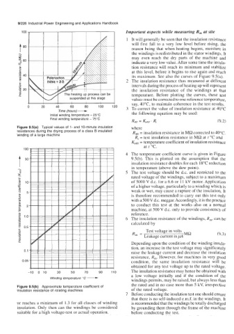
Figure 9.5(a) Typical values of 1- and 10-minute insulation where
resistances during the drying process of a class B insulated R4, = insulation resistance in MR corrected to 40°C.
winding of a large machine
R, = test insulation resistance in MR at t "C and
Kt40 = temperature coefficient of insulation resistance
at t "C.
100
4 The temperature coefficient curve is given in Figure
9.5(b). This is plotted on the assumption that the
insulation resistance doubles for each 18°C reduction
T 50
in temperature (above the dew point).
5 The test voltage should be d.c. and restricted to the
rated voltage of the windings, subject to a maximum
of 5000 V d.c. for a 6.6 or 11 kV motor. Application
of a higher voltage, particularly to a winding which is
weak or wet, may cause a rupture of the insulation. It
is therefore recommended to carry out this test only
with a 500V d.c. meggar. Accordingly, it is the practice
to conduct this test at the works also on a normal
machine, at 500 V d.c. only to provide consistency of
reference.
6 The insulation resistance of the windings, R,, can be
calculated by
Test voltage in volts
R, = MR (9.3)
Leakage current in ,uA
Depending upon the condition of the winding insula-
tion, an increase in the test voltage may significantly
0.1 raise the leakage current and decrease the insulation
resistance, R,. However, for machines in very good
0.05 condition, the same insulation resistance will be
Winding temperature "C - obtained for any test voltage up to the rated voltage.
The insulation resistance may hence be obtained with
-10 0 10 30 50 70 90 110 a low voltage initially and if the condition of the
windings permits, may be raised, but always less than
Figure 9.5(b) Approximate temperature coefficient of the rated and in no case more than 5 kV, irrespective
insulation resistance of rotating machines of the rated voltage.
7 Before conducting the insulation test one should ensure
that there is no self-induced e.m.f. in the windings. It
or reaches a minimum of 1.3 for all classes of winding is recommended that the windings be totally discharged
insulation. Only then can the windings be considered by grounding them through the frame of the machine
suitable for a high voltage-test or actual operation. before conducting the test.