
Page 255 - Industrial Power Engineering and Applications Handbook
P. 255
10/234 Industrial Power Engineering and Applications Handbook
Table 10.2 Shaft and bearing housing diameters and their
tolerances, to provide a tight or shrink fit to the bearings
Deep groove hull hearings Cylindrical roller bearings
(A) Shaft diameter Tolerunce (A) Shaft diameter lhlerance
Up to 18 mm j, Up to 40 mm kS
Above 18-100 mm k, Above 40-160 mm ni5
Above 100-160 mm m5 Above 160-200 mm tij
(B) Housing bore (Bj Housing bore
dicimeter diameter
All sizes h6 or j6 All sizes h6 Or j6
Pull
Based on IS0 286- I
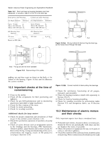
Figure 10.3(a) Wrong method of dismounting the bearings,
as the forces travel through the balls
Note The jig can also be motor operated
Figure 10.2 Dismounting of the pulley
pulling out and thus exert no thrust on the balls or the
rollers of the bearing. Figure 10.3(a) and (b) illustrate L Pull Pull 1
the correct method.
Figure 10.3(b) Correct method of dismounting the bearings
10.2 Important checks at the time of
commissioning Check for satisfactory functioning of all gauges,
indicators and recorders.
Clean up the motor. Check for bearing insulation (dealt with separately in
Check all the components for their positioning and Section 10.4.5).
tightness. Check for bearing housing grounding.
Check for pre-lubrication/grease and its monitoring Check for winding insulation by polarization index
attachment (provided in large machines). (Section 9.5) and dissipation factor, tan 6 (Section
Check for free rotation of the rotor. 9.6)
Check for motor grounding.
Check for winding insulation.
10.3 Maintenance of electric motors
Additional checks for large motors and their checks
Check for proper connection and circulation of fluid
or gas in the coolant circuit (Section 1.16). Only important aspects have been considered here:
Check for satisfactory operation of auxiliary oil pump
and fan. Protected-type motors, located in dusty environments,
Check all safety devices such as temperature sensors should be blown out periodically with clean and dry
in the windings and the bearings, PTC thermistors, air. Replace the motor, if possible.
vibration probes, space heaters and coolant circuit, for Check the protective equipment for any worn parts or
their correct fitting, wiring and functioning of the alarm, contacts and their tightness.
annunciation and tripping circuit of the protective Check the condition of the cable insulation, its termination
switchgear (Section 12.8). andjointing. Motor connections should always be made