
Page 414 - Industrial Power Engineering and Applications Handbook
P. 414
13/388 Industrial Power Engineering and Applications Handbook
Water 12-14"C
Condenser
liquid
Compressed
hot-gas Chilled
water
Condenser Pump
Compressor 11
Cold condenser
Super heated gas water
Expansion .
valve
Chiller Condenser I -
Air 21-24°C
water
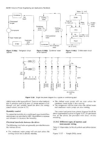
Figure 13.49(a) Refrigerant circuit Figure 13.49(b) Condenser water Figure 13.49(c) Chilled water circuit
(typical) circuit (typical) (typical)
Air handling
unit
Figure 13.50 Single line power diagram for a typical air conditioning plant
chilled water to the required level. There are other methods The chilled water pump will not start unless the
also in practice such as by pass of certain amount of air condenser water pump is also running.
through coil and variable speed fan drive (for energy The compressor will not start unless the chilled water
conservation) (section 6.15). and condenser water pumps are also running.
Humidity control The control and protection scheme diagram for all the
To control the humidity in a conditioned space humidifiers above requirements is given in Figure 13.5 1. It is presumed
reheaters are provided Humidifiers to increase that all the drives are provided with direct on-line
and reheaters to decrease the humidity. switching.
Electrical interlocks between the drives 13.10.2 Different types of starters and
instruments wiring
The following interlocks are generally provided between
the various drives: Table 13.16 provides the list of symbols and abbreviations
used.
The condenser water pump will not start unless the
cooling tower fan is already running. Figure 13.52 - Simple DOL starter