
Page 410 - Industrial Power Engineering and Applications Handbook
P. 410
13/384 Industrial Power Engineering and Applications Handbook
IIC-I
(52i)
(52iii)
I
(52ii) I I
I
I
I
(52ii) I
I
I
. .
IIC-I BIC IIC-2
(52i) (52iii) (52ii)
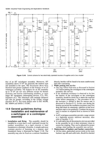
Figure 13.46 Control scheme for two electrically operated sources of supplies and a bus coupler
that of an HT switchgear assembly. Moreover, HT directly, but this will be found to be more cumbersome
assemblies above 33 kV are generally the outdoor type and time-consuming.
and installed in the open. The discussions above have 2 While putting into service
therefore laid greater emphasis on the features of an LT One may follow field tests as discussed in Section
switchgear assembly. The features for an HT assembly 14.5 before putting the switchgear or the controlgear
up to 33 kV are not very different except for thicker assembly into service.
enclosure and heavier load-bearing members, to carry If the insulation resistance is observed to be low
larger HT equipment (interrupting devices, CTs, PTs, the interior of the switchgear or the controlgear
insulators etc.). The clearances and creepage distances assembly should be dried out to attain the required
will also be greater, according to the system voltage value before energizing it. The procedure to dry
(Section 28.5.2). For more details refer to IEC 60298, the moisture is similar to that for motors and is
IEC 60694 and ANSI-C-37/20C. discussed in Section 9.5.2. In this case during the
heating-up period the insulation resistance may first
drop and reach its minimum, stabilize at that level
13.9 General guidelines during and then start to rise gradually. Continue the process
installation and maintenance of until it reaches its required level as shown in Table
14.7.
a switchgear or a controlgear In HT switchgear assemblies provide a surge arrester
assembly or a lightning arrester, wherever necessary. Also
refer to Section 17.11.
1 Installation and fixing The assembly should be It is advisable that all the protective devices provided
installed in a room that is well ventilated (except for in the assembly be set to their minimum values to
outdoor assemblies), on a rigid concrete or steel ensure fast tripping. They can be adjusted for proper
foundation to eliminate vibrations. A simple and more settings when putting the assembly into service.
common practice of fastening on a separate steel 3 Maintenance of busbars and busbar connections
foundation frame is illustrated in Figure 13.48. The All the joints, particularly power joints at the main
assembly may also be fixed on a concrete foundation busbars, tap-offs and cable ends, should be checked