
Page 409 - Industrial Power Engineering and Applications Handbook
P. 409
Switchgear and controlgear assemblies 13/383
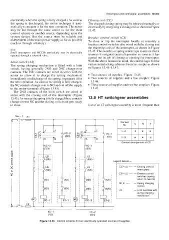
electrically when the spring is fully charged.) As soon as Closing coil (CC)
the spring is discharged, the motor recharges it auto- The charged closing spring may be released manually or
matically to prepare it for the next operation. The motor electrically by energizing a closing coil as shown in Figure
may be fed through the same source as for the main 13.45.
control scheme or another source, depending upon the
system design. But the source must be reliable and Breaker control switch (CS)
independent of the main power supply as far as possible To close or trip the interrupter locally or remotely a
(such as through a battery). breaker control switch is also wired with the closing and
the shunt trip coils of the interrupter, as shown in Figure
Note 13.45. The switch is a spring return type to ensure that it
Small interrupters and MCCBs particularly may be electrically
operated through a solenoid valve. resumes its original (neutral) position as soon as it has
carried out its job of closing or opening the interrupter.
Limit switch (LS) With the above features in mind, the control logic for the
The spring charging mechanism is fitted with a limit various interlocking schemes becomes simple as shown
switch, having generally 2N0 and 2NC change-over in Figures 13.45-13.47:
contacts. The 2NC contacts are wired in series with the
motor to allow it to charge the spring mechanism Two sources of supplies: Figure 13.45.
immediately on discharge of the spring, to prepare it for Two sources of supplies and a bus coupler: Figure
the next operation. As soon as the spring is fully charged, 13.46.
the NC contacts change over to NO and cut off the supply Three sources of supplies and two bus couplers: Figure
to the motor terminals (Figure 13.45). 13.47.
The 2N0 contacts of the limit switch are wired in
series with the closing coil of the interrupter (Figure
13.45). As soon as the spring is fully charged these contacts 13.8 HT switchgear assemblies
change over to NC and the closing coil circuit gets ready
to close. Use of an LT switchgear assembly is more frequent than
sw-1
!f-+ 7'
T
I
I
I
Contact
...........
f I/C-2 h N ............... IK-I
(52ii) "{ ...........-.. (52i) 1 -B
I Contact arrangement of CS
I/C-2
(52ii)
LE ?nd details:-
CC-I ,2, ----- - Closing coils of
interrupters
__-_ CS-1,2, ----- - Breaker control
I switches (spring
I
return to neutral)
1 I M1,2, ----- - Spring charging
I I
I (52i) I motors
I LS - Limit switches with
I I spring charging
I I
I mechanism
1 I cc-I j ST-1
I-- _--_ t---- ~
VC-I I/C-2
(52i) (52ii)
Figure 13.45 Control scheme for two electrically operated sources of supplies