
Page 404 - Industrial Power Engineering and Applications Handbook
P. 404
13/378 Industrial Power Engineering and Applications Handbook
13.7.4 Requirements other than constructional
features
Mechanical and electrical interlocks
An industrial load having a connected load
requirement of more than 2000 kVA may normally
call for more than one feeding transformer for
limiting the fault level of the system, as discussed
in Section 13.4.1(5). It may also have a standby
emergency source of supply. The two feeding
transformers, although they may be identical
electrically and suitable for parallel operation,
are not supposed to run in parallel with a view to
limiting the fault level. The emergency source,
as a result of different electrical parameters, is
not run in parallel with any of the two incoming
sources. To achieve the required safety by avoiding
a parallel operation, it is essential to provide a
mechanical or an electrical interlock or both
between all the incoming feeders. Schemes to
achieve the required safety interlocks are described
in Section 13.7.5.
When there are more than one sources of supply,
it is recommended to distribute the loads also in
as many sections as the incomers, and provide a
tie-circuit between every two sections, to obtain
more flexibility. Now fault on one section or
source of supply will not result in the loss of
power to the entire system. Figures 13.16 and
13.17 illustrate this type of distribution. or straight through joints
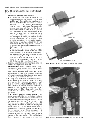
transformers must be provided with Figure 13.37(a) Pressfit SMC/DMC shrouds for busbar joints
current limiting fuses at both ends.
Control wiring Wiring from supervisory or annun-
ciator devices to the terminal blocks may be carried
out with smaller wires, as may be recommended for
such devices. However, they should run through
separate wire bunches, and not through the bunches
of control wires for easy identification and to remain
unaffected by heat of control wires.
For easy identification and prompt maintenance it
is mandatory to segregate all control wires when
they are carrying more than one control supply
(e.g. at different voltages and both a.c. and d.c.),
and run them in separate bunches. The control
wires must also be of different colours for different
control supplies. The colour codes have been
standardized for different control sumlies (refer to
IEC 60445).
Space heaters with temperature control These
are recommended with a view to eliminate condensa-
tion of moisture, particularly when the switchgear
is idle and the atmosphere is humid. The space heaters
are normally rated for Vr/fi, 40 W, single phase.
They are located appropriately such as in the cable
alley, and are switched ON when the switchgear is
likely to be idle for a long period. The number of
space heaters will depend upon the size and type of
the switchgear. For a cubicle-type panel, it is
recommended that at least one space heater be
provided in each vertical panel. They should be
mounted at the lower portion of the panel for better
heat Circulation through natural heat Convection. Figure 13.37(b) SMCIDMC shrouds for bus joints and tap-offs