
Page 400 - Industrial Power Engineering and Applications Handbook
P. 400
13/374 Industrial Power Engineering and Applications Handbook
Note with a view to providing more space within the feeder
For instrument modules, relay and control modules or control panels to achieve larger clearances between the live parts
or all power modules, where an interlock with the door is not and to lessen the chances of a fault during normal
possible or is not provided, a proper shroud or shutter must be operation, besides providing extra working space.
provided on all exposed live parts rated above 240 V. 6 The operating height of each operable mount, i.e.
the centreline of the breaker or the switch handle
To provide a folded and extensible construction to and pushbuttons or reset buttons, including the reset
allow for ease of alteration and extension of assem- probe of a protective relay on the feeder doors, is
blies at site in future, if required. recommended to be no higher than 1900 mm from
To have a modular construction with a wide choice ground level. This is an operational requirement for
of module sizes for optimum utilization of the usable ease of operation.
area in each vertical panel, which is normally 7 The height (we may consider it from the bottom
1800 mm as illustrated in Figure 13.32. The general line) of the indicating instruments such as a voltmeter
practice is to have the module sizes in the ratio of and an ammeter, which the operator may have to
1/6 (300 mm), 1/4 (450 mm), 1/3 (600 mm) and read often, is also recommended to be no higher
1/2 (900 mm), etc. Some manufacturers, however, than 2000 mm or less than 300 mm from ground
supply 1/8 (225 mm) and 1/9 (200 mm) size of level.
modules when the sizes and number of components 8 The terminals provided to receive cables to make
for a module are less and can be accommodated in external connections, may preferably be located no
such a small module size. For critical installations, less than 200 mm (at the terminal centreline) from
however, such as for a refinery or a petrochemical the gland plate.
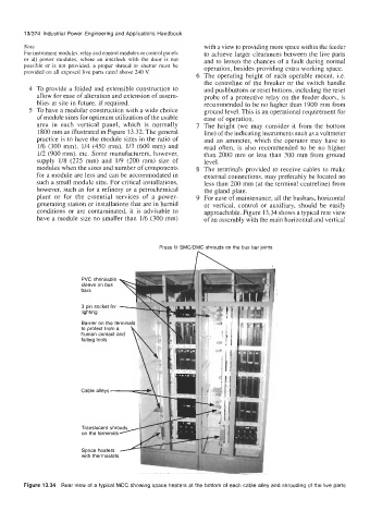
plant or for the essential services of a power- 9 For ease of maintenance, all the busbars, horizontal
generating station or installations that are in humid or vertical, control or auxiliary, should be easily
conditions or are contaminated, it is advisable to approachable. Figure 13.34 shows a typical rear view
have a module size no smaller than 1/6 (300 mm) of an assembly with the main horizontal and vertical
Press fit SMC/DMC shrouds on the bus bar joints
PVC shrinkable
sleeve on bus
bars
3 pin socket for
lighting
Barrier on the terminals
to protect from a
human contact and
falling tools
Cable alleys -
Translucent shro
on the terminals
Figure 13.34 Rear view of a typical MCC showing space heaters at the bottom of each cable alley and shrouding of the live parts