
Page 402 - Industrial Power Engineering and Applications Handbook
P. 402
13/376 Industrial Power Engineering and Applications Handbook
to the main ground bus and each individual feeder 3 Guide rails are telescopic and are necessary to ensure
must be bolted through this. Figure 13.35 illustrates this safe and aligned movement of the trolley while
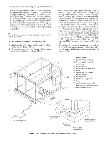
arrangement through one module of a vertical panel. racking it in or out of its module to avoid misalign-
3 Door grounding Similarly, Ihe door is also a part of ment of the moving contacts. A misalignment may
the main frame and is automatically grounded through cause an inadvertent contact of the draw-out contacts
the mounting hinges and the door closing knobsllatches with the adjacent fixed contacts of the other phases,
etc. But a separate door ground wire connecting the which are mounted on the live vertical bus (Figure
frame is now also recommended. Where, however, 13.35) and may cause a flashover and a short-circuit.
there is no door wiring, no additional door grounding 4 The chassis for both fully draw-out and semi-draw-
is essential. out MCCs is fitted with self-aligning plug-in-type
high-pressure contacts for incoming and outgoing
Note power connections. The control terminals for control
For more details on grounding and the grounding practices, refer to connections are the manually connected, plug-in type
Chapters 21 and 22. in semi-draw-out-type MCC, as shown in Figure
13.13(a) and spring-loaded sliding-type in a fully
13.7.3 Essential features of a draw-out MCC draw-out MCC, as shown in Figures 13.13(b) and
(c).
1 All power and controlgears are mounted on withdra- 5 It is preferable to provide a cranking or a push-in
wable chassis (Figure 13.36). device with a latching arrangement to lock the trolley
2 The chassis moves on low-friction rolling mounts in both service and isolated positions, as shown in
or guide rails (Figures 13.2 and 13.36). Figure 13.36.
Test position
(front slot)
Details at ‘D’
Latching device
Figure 13.36 Front view of a typical withdrawable chassis (trolley)