
Page 406 - Industrial Power Engineering and Applications Handbook
P. 406
131380 Industrial Power Engineering and Applications Handbook
:i 2 locks : 5 locks :
pLJD
El
I/C - 2 3 keys :
P
( (52ii) IA-l
1
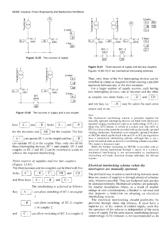
2 1" Figure 13.41 Three sources of supply and two bus couplers
Figure 13.39 Two sources of supply
r Figures 13.39-1 3.41 are mechanical interlocking schemes
IA-l
switched at a time as required without causing a parallel
I- c 3 locks : Thus, only three of thc five interrupting devices can be
I-BI operation between any of the two incomers.
For a larger number of supply sources, each having
two interrupting dcvices, one as incomer and the other
as coupler, two more locks, i.e. and Fi
(52iii)
n
D
may be added for each extra
m and one key, Le. Lll
source and so on.
Figure 13.40 Two sources of supply and a bus coupler
Note
The mechanical interlocking xheme is generally required for
keys 14-1 and m: locks IA-1 and Fl manually operated interrupting devices not fitted with electrically
operated tripping mechanisms such as an undervoltage (U/V) or a
shunt trip (S/T) release. A switch or a switch fuse unit (SFU or
U tripping mechanism. Sometimes even manually operated breakers
for the incomers and AB for the coupler. The key FSU) is a device that cannot be provided with an electrically operated
or MCCBs which can be fitted with an UN or S/T are required to
IA] can operate UC-1 or the coupler and key have a mechanical interlocking scheme, although this is not a
I-B1 preferred method when an electrical interlocking scheme is possible.
can operate I/C-2 or the coupler. Thus, only two of the This aspect is discusscd later.
three interrupting devices, I/C-1 and coupler, I/C-2 and When the breaker (including an MCCB) is provided with an
coupler, or I/C-1 and I/C-2 can be switched at a time to electrical closing mechanism through a motor or a solenoid,
achieve the required interlocking. mechanical interlocking is not recommended as mechanical
interlocking will make electrical closing redundant, for obvious
reasons.
Three sources of supplies and two bus couplers
(Figure 13.41) Electrical interlocking scheme (when the
The three incomers and two couplers can be fitted with five interrupters are manually operated)
locks, m, PI, m, and The preferred way to achieve interlocking between more
and three keys VI, I/, and )I. than one source of supplies is through electrical schemes
only, wherever possible. They are foolproof and can also
be operated remotely. Mechanical schemes are generally
The interlocking is achieved as follows: for smaller installations where, as a result of smaller
ratings or cost considerations, a breaker is not used and
Key 1 A- 1 -can allow switching of I/C-1 or coupler
that imposes a limitation on adopting an electrical
1 interlocking scheme.
The electrical interlocking should preferably be
- can allow switching of I/C-2, coupler provided through shunt trip releases. It must have a
1 or coupler 2 separate a.c. or d.c. source of control supply, such that
the operation of the scheme ib independent of the main
and 1 C - I can allow switching of I/C-3 or coupler 2 source of supply. For the same reason, interlocking through
undervoltage (UN) releases is not recommended as its