
Page 401 - Industrial Power Engineering and Applications Handbook
P. 401
Switchgear and controlgear assemblies 13/375
buses and Figure 13.2, illustrates the front of the interlocking is required to ensure that the feeder door
same assembly with two sets of single-phase control does not open when the feeder is live.
buses. Similarly, it must not be possible to switch the feeder
IO Also the cable alley should be easily accessible to ON when feeder door is open.
make cable connections, and facilitate easy mainte- A defeat mechanism to bypass the door interlock may
nance and regular checks, as illustrated in Figures also be necessary for the purpose of testing.
13.2 and 13.34. Padlocking arrangements may be required to lock the
11 Shrouds are recommended in the front and on the feeder in the OFF position when the machine is
top of the terminals of each feeder to provide undergoing a shutdown or repairs.
protection to the operator from live parts. They will Refer to Figure 13.12 showing these features.
also prevent the tools falling inadvertently from an
upper module onto the live terminals of the lower Protection from electric shocks (grounding system)
module. Look closely at Figure 13.34 for these
features, where in the front is provided a typical 1 Main grounding The provision of a grounding
arrangement is mandatory through the length of the
translucent shroud to enable a check of the terminals, panel. It may be of aluminium, galvanized iron (GI)
without opening the shroud. On top is provided or copper. (See also Section 22.4.)
another shroud to prevent the terminals from falling 2 Grounding of each feeder The most effective system
tools. If the shroud is of polycarbonate (acrylic has is to ground each feeder with the main ground bus at
a low temperature index), it should be suitable to one point at least. It is important to note that each
withstand a temperature of up to 200°C without feeder is grounded automatically through the metallic
deformation. This temperature may be reached during supports of the assembly, on which are bolted all the
a fault at the terminals.
switchgear components (the whole assembly is already
12 For safety reasons, the busbar chamber and the cable grounded). For an ideal condition, an additional
alley should be separate and shrouded from each
other. grounding of the components should normally not be
13 Where wires or conductors may pass through a metal required but this grounding may not be foolproof due
to the painted frame on which the switchgear compo-
sheet, a rubber grommet, bushing or other mechanical
protection should be provided to prevent the wires nents are mounted. It is possible that the components
from insulation damage. may not make a perfect ground contact through the
body of the switchgear frame and it is therefore
recommended that each comDonent is seuaratelv
Mechanical interlocks grounded. For a cubicle design, a separate ground
Provisions must be made for safety features such as bus of a smaller section than the main ground bus
padlocking and door interlocking arrangements. Door may be run through each vertical section and connected
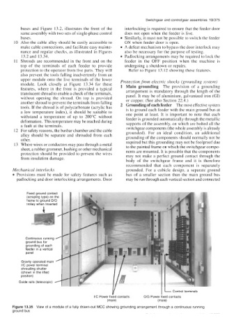
Figure 13.35 View of a module of a fully drawn-out MCC showing grounding arrangement through a continuous running
ground bus