
Page 398 - Industrial Power Engineering and Applications Handbook
P. 398
13/372 Industrial Power Engineering and Applications Handbook
rating. The sizes selected must then be counter checked Horizontal
for their mechanical endurance to sustain the fault busbar
conditions of the system or the circuits on which they chamber
are connected, depending upon the protective scheme
adopted and its time of isolation on fault (Le. 1 s, 3 s or
current limiting) as discussed above.
The ratings and sizes of main components and cables
can be selected from manufacturers' catalogues. But cables
required for the switchgear internal control and power
wirings, being typical of all, are normally identified by
their cross-sectional area rather than the current ratings.
We have therefore provided the technical data and current
ratings for the most common sizes of such cables for a
ready reference in Table 13.15.
13.7.2 Design considerations for switchgear
assemblies
Below we discuss briefly the constructional requirements
and general manufacturing practices for cubicle-type
switchgear and controlgear assemblies, and the electrical
and the mechanical design considerations to comply with
the above design parameters and service conditions.
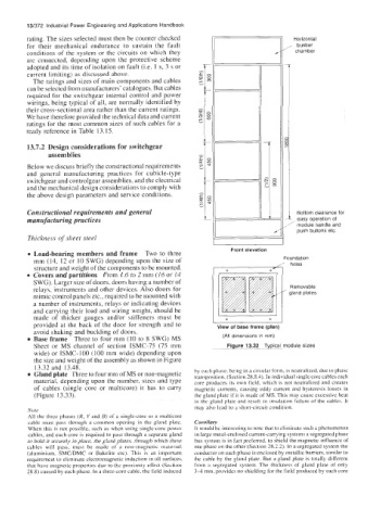
Constructional requirements and general Bottom clearance for
manufacturing practices easy operation of
module handle and
push buttons etc.
Thickness of sheet steel
I I
Front elevation
Load-bearing members and frame Two to three
Foundation
mm (14, 12 or 10 SWG) depending upon the size of / holes
structure and weight of the components to be mounted. +
Covers and partitions From 1.6 to 2 mm (16 or 14 +I
SWG). Larger size of doors, doors having a number of
relays, instruments and other devices. Also doors for
mimic control panels etc., required to be mounted with
a number of instruments, relays or indicating devices
and carrying their load and wiring weight, should be
made of thicker gauges and/or stiffeners must be 1' +
provided at the back of the door for strength and to View of base frame (plan)
+
avoid shaking and buckling of doors.
Base frame Three to four mm (10 to 8 SWG) MS (All dimensions in rnm)
Sheet or MS channel of section ISMC-75 (75 mm Figure 13.32 Typical module sizes
wide) or ISMC-100 (100 mm wide) depending upon
the size and weight of the assembly as shown in Figure
13.32 and 13.48.
Gland plate Three to four mm of MS or non-magnetic by each phase, being in a circular form, is ncutralized, due to phase
tranuposition, (Section 28.8.4). In individual single core cables each
material, depending upon the number, sizes and type core produces its own field, which is not neutralized and creates
of cables (single core or multicore) it has to carry magnetic currents. causing eddy current and hysteresis losses in
(Figure 13.33). the gland plate if it is made of MS. This may cause excessive heat
in the gland plate and result in insulation failure of the cables. It
may also lead to a short-circuit condition.
Note
All the three phases (R, Y and B) of a single-core or a multicore
cable must pass through a common opening in the gland plate. Corollary
a
When this is not possible, such as when using single-core powei- It would bc interesting to note that to eliminate SUC~ phenomenon
cables, and each core is required to pass through a separate gland in large metal-enclosed current-carrying systems a segregated phase
to hold it securely in place, the gland plates, through which these bus system is in fact preferred, to shield the magnetic influence of
cables will pass, must be made of a non-magnetic material one phase on the other (Section 28.2.2). In a segregated system the
(aluminium, SMC/DMC or Bakelite etc). This is an important conductor on each phase is enclosed by metallic barriers, similar to
requirement to eliminate electromagnetic induction in all surfaces the cable by the gland plate. But a gland plate is totally different
that have magnetic properties due to the proximity effect (Section from a segregated system. The thickness of gland plate of only
28.8) caused by each phase. In a three-core cable, the field induced 3-4 mm, provides no shielding for the field produced by each core