
Page 394 - Industrial Power Engineering and Applications Handbook
P. 394
13/368 Industrial Power Engineering and Applications Handbook
in Section 13.4.2 to arrive at the most appropriate
sizes of components, bus sections, etc.
13.6 Designing a bus system
We discuss in detail in Chapter 28, the procedure to I N
design a bus system, including its mounting and supporting
structure and hardware for a required fault level. Elevation Sectional
(a) view
13.6.1 Constructional features of a bus system
(i) Busbars and wireways
In the cubicle construction of a switchgear assembly the
busbar chamber is normally located at the top of the
assembly and runs through the length of it. It is usually
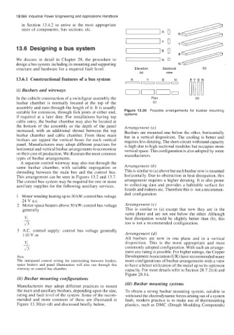
suitable for extension, through fish joints at either end, Figure 13.30 Possible arrangements for busbar mounting
if required at a later date. For installations having top systems
cable entry, the busbar chamber may also be located at
the bottom of the assembly or the depth of the panel Arrangement (a)
increased, with an additional shroud between the top Busbars are mounted one below the other, horizontally
busbar chamber and cable chamber. From these main but in a vertical disposition. The cooling is better and
busbars are tapped the vertical buses for each vertical requires less derating. The short-circuit withstand capacity
panel. Manufacturers may adopt different practices for is high due to high sectional modulus but occupies more
horizontal and vertical busbar arrangements to economize vertical space. This configuration is also adopted by some
on their cost of production. We illustrate the most common manufacturers.
types of busbar arrangements.
A separate control wireway may also run through the
same busbar chamber, with suitable segregation or Arrangement (b)
shrouding between the main bus and the control bus. This is similar to (a) above but each busbar now is mounted
This arrangement can be seen in Figures 13.2 and 13.7. horizontally. Due to obstruction in heat dissipation, this
The control bus system may be required for one or more arrangement requires a higher derating. It is also prone
auxiliary supplies for the following auxiliary services. to collecting dust and provides a habitable surface for
lizards and rodents etc. Therefore this is not a recommen-
ded configuration.
Motor winding heating up to 30 kW: control bus voltage
24 V a.c.
Motor space heaters above 30 kW: control bus voltage Arrangement (c)
generally This is similar to (a) except that now they are in the
v, same plane and are not one below the other. Although
heat dissipation would be slightly better than (b), this
43 too is not a recommended configuration.
A.C. control supply: control bus voltage generally
llOV or Arrangement (d)
All busbars are now in one plane and in a vertical
disposition. This is the most appropriate and most
commonly adopted configuration. With such an arrange-
ment any rating is possible. For higher ratings, the Copper
Note Development Association (UK) have recommended many
The interpanel control wiring for interlocking between feeders, more configurations of busbar arrangements with a view
space heaters and panel illumination will also run through this to have a better utilization of the metal up to its optimum
wireway or control bus chamber. capacity. For more details refer to Section 28.7.2(iii) and
Figure 28.14.
(ii) Busbar mounting configurations
(iii) Busbar mounting systems
Manufacturers may adopt different practices to mount
the main and auxiliary busbars, depending upon the size, To obtain a strong busbar mounting system, suitable to
rating and fault level of the system. Some of the recom- withsland the electrodynamic forces arising out of a system
mended and more common of these are illustrated in fault, modern practice is to make use of thermosetting
Figure 13.30(a)-(d) and discussed briefly below, plastics, such as DMC (Dough Moulding Compounds)