
Page 393 - Industrial Power Engineering and Applications Handbook
P. 393
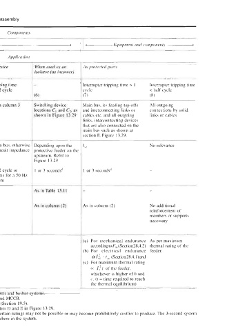
Components
 <   Interrupting devices   >  1  -Equipment   and components A
   Application
 When used as a protective device   When used as a protected device   When used as an   As protected parts
 (as incomer)   'as outgoing)'   isolator (as incomer)

 Parameters   Tripping time   Tripping time   Tripping time   Tripping time   Interrupter tripping time > 1   Interrupter tripping  time
 > 1 cycle   < half cycle   > 1 cycle   < 1/2 cycle   cycle   < half cycle
 (1)   (2)   (3)   (4)   (5)   (7)             (8)
 Type of devices   OCBs", ACBs,   MCCBs,   As in column 2   As in column 3   Switching device   Main bus, its feeding tap-offs   All outgoing
 MCCBs in LT and   MCBs in LT and HRC   locations  C, and  Cz, as  and interconnecting links or   connections by  solid
 MOCBS~   fuses in both LT   Fhown in Figure 13.29   cables etc. and all outgoing   links or cables
 ABCBsb, SF,  and   and HT   links, interconnecting devices
 VCBs in HT               that are also connected on the
                          main bus such as shown at
                          section F, Figure  13.29.
 1,  Short-time rating   I,,,   if connected on the main bus, otherwise  Depending upon the   No relevance
 or symmetrical   < Isc  depending upon the circuit impedance  protective feeder on the
 fault level   I,,   upstream. Refer to
            Figure  13.29
 2  Duration of fault   1 or 3 secondsd   <half cycle or   1 or 3 secondsd   < 1/2 cycle or   I  or 3 secondsd   1 or 3 secondsd   -
 < 5 ms for a   < 5 ms for a 50 Hz
 t5'
 50 Hz system   system
                          I-
 -
 3  Making capacity  I,  As in Table  13.1 I   As in Table  13. I1   As in Table 13.1 1
 -
 4  Endurance of   According  to   As in column (2)   -   As in column (2)   As in column (2)   No additional
 supporting and   electrodynamic forces,       reinforcement of
 mounting structure,   F,,  = I;  equation     members or supports
 load-bearing                                  necessary
 members and   (28.4)
 hardware
 5  Cross-sectional  area   Taken care of by the manufacturer of the devices   (a)  For  mechanical  endurance  As per maximum
 of current-carrying         a~cordingtoF~(Section28.4.2) thermal rating of the
 metallic links or         (b) For  electrical  endurance  feeder.
 cables                      ~rl: I,, (Section28.4.l)and
                           (c)  For maximum thermal rating
                             =  I:t  of the feeder,
                             whichever is higher of b and
                             c. (I = time required to reach
                             the thermal eauilibrium)
 Figure 13.29 illustrates  a typical power distribution scheme to assign ratings to the various devices, components and husbar systems.
 Wse of these breakers is gradually  waning in the light of more advanced technologies available in an ACB and MCCB.
 bUse of these breakers is also waning  in  the light of more advanced technologies available in SF,  and VCBs (Section 19.5).
 'These  protect the circuits in the lower stream and are protected  by a device in the upper stream such as feeders D and E in Figure 13.29.
 dNormally only a I-second system is in use. The 3-second  system is severe, for which protective devices in certain ratings may not be possible or may become  prohibitively  costlier to produce.  The 3-second system
 may, however, be used for a generator circuit to protect the generating source from a fallout on a fault elsewhere in the system.