
Page 397 - Industrial Power Engineering and Applications Handbook
P. 397
Switchgear and controlgear assemblies 131371
busbar systems, however, a more elaborate exercise would conducting parts, such that the clearances and
be necessary in high rating systems, 1600 A and above, creepages now achieved are no less than as specified
due to skin and proximity effects as discussed in Section in Tables 28.4 and 28.5.
28.6.3. The current-carrying conductors are covered with
an insulation suitable for withstanding a one-minute
13.6.3 Complying with design parameters power frequency voltage as in Tables 13.2 and 14.3
for series I and 14.1 and 14.2 for series I1 voltage
Rated voltage and frequency systems.
Any provision or arrangement that can withstand
The switchgear assembly, its components and the bus the one-minute power frequency voltage as in these
system must be designed for the rated voltage and tables at a lesser clearance or creepage distances
frequency. than specified in Tables 28.4 and 28.5, such as by
providing extra insulation wherever necessary. To
Rated insulation level obtain clearances for open-type outdoor and neutral
grounding switchgears, refer to BS 7354.
To comply with the rated insulation level, all the current-
carrying components forming part of the assembly should
have clearances and creepage distances according to their 13.7 Designing a switchgear
relevant standards whereas busbars and busbar connections assembly
must have the distances noted below.
Clearance and creepage distances for 13.7.1 Rated continuous current rating and
air-insulated busbars permissible temperature rise
The clearances and creepage distances should be main- The rating of current-canying devices and components
tained as shown in Tables 28.4 and 28.5. These values should be selected according to the continuous current
can be reduced when: they have to carry and the duty they have to perform.
Deratings, depending upon the service conditions, should
(a) A barrier of insulation is provided between the also be applied when deciding their continuous current
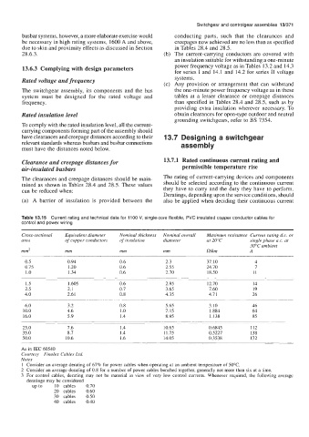
Table 13.15 Current rating and technical data for 1100 V, single-core flexible, PVC insulated copper conductor cables for
control and power wiring
Cross-sectional Equivalent diameter Nominal thickness Nominal overall Maximum resistance Current rating d.c. or
area of copper conductors of insulation diameter at 20°C single phase a.c. at
30°C ambient
mm2 mm mm mm nlkm A
0.5 0.94 0.6 2.3 37.10 4
0.75 1.20 0.6 2.55 24.70 7
1 .o 1.34 0.6 2.70 18.50 11
1.5 1.605 0.6 2.95 12.70 14
2.5 2.1 0.7 3.65 7.60 19
4.0 2.61 0.8 4.35 4.7 1 26
6.0 3.2 0.8 5.65 3.10 46
10.0 4.6 1 .o 7.15 1.884 64
16.0 5.9 1.4 8.95 1.138 85
25.0 7.6 1.4 10.65 0.6845 112
35.0 8.7 1.4 11.75 0.5227 138
50.0 10.6 1.6 14.05 0.3538 172
As in IEC 60540
Courtesy Finolex Cables Ltd.
Notes
1 Consider an average derating of 67% for power cables when operating at an ambient temperature of 50°C.
2 Consider an average derating of 0.8 for a number of power cables bunched together, generally not more than six at a time.
3 For control cables, derating may not be material in view of very low control currents. Whenever required, the following average
deratings may be considered
up to 10 cables 0.70
20 cables 0.60
30 cables 0.50
40 cables 0.40