
Page 405 - Industrial Power Engineering and Applications Handbook
P. 405
Switchgear and controlgear assemblies 13/379
Figure 13.34 illustrates a likely location for such a capacity of the busbar system. Painting is not a
heater. To prevent condensation of moisture they measure of safety but a technique to enhance the
are recommended to reach a temperature rise of only current carrying-capacity of the busbar system. For
5-1 0°C above the ambient temperature, inside the safety during maintenance, some other form of
housing and are controlled automatically through a shrouding can be provided, such as by providing
pre-set thermostat. SMC/DMC shrouds at all such places where the
A three-pin socket, rated for Vr18, 5 A, may also be live bus may be exposed to the operator attending to
provided for panel lighting or hand lamp (Figure maintenance work.
13.34). 9 For precautions in making joints, refer to Section 29.2.
Panel numbering on acrylic sheet or aluminium 10 Painting. A thorough surface treatment of the sheet-
anodized plates may be fixed on the front and the metal and a good painted surface are prerequisites
rear of each vertical panel for quick identification for equipment to provide long years of operation.
of each panel section (Figure 13.1). For the benefit of those in the field of manufacturing
For safety to personnel during maintenance and to of such assemblies, we have provided a brief proce-
protect the live system from lizards and rodents the dure for the sheet treatment and surface painting of
busbars may be covered with PVC tape or heat- these assemblies in the Appendix.
shrinkable PVC sleeve. The joints and the tap-offs
can be protected through SMCDMC shrouds, as The above are the more obvious constructional, design
shown in Figure 13.37. The PVC taping, however, and safety features for a switchgear or a controlgear
is not recommended for it may suffer cuts or tear assembly. For more details and additional requirements
off during working on the busbars and become loose refer to IEC 60439-1 for LT, IEC 60298 and IEC 60694
or worn with time. PVC sleeving is a more for HT and ANSI-C-37/20C, common for LT and HT
recommended practice but sleeving may impose switchgear and controlgear assemblies.
limitations. It is possible that one may not be able to
provide a true skin-fit sleeve through the length of
the busbars, which may affect its cooling. At certain 13.7.5 Interlocking of feeders to prevent parallel
places, it may have air bubbles from where it will operation
provide a reduced heat dissipation.
For higher rating systems, say 2500 A and above, Mechanical interlocking scheme
sleeving is normally not used. Instead, a non-metallic,
semi-glossy black paint may be provided to make Use of castle locks
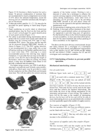
the bus conductors act like a black body and dissipate Different figure locks such as m,
more heat. This will also add to the current-carrying and
a
are used with a common master key
(Figure 13.38). The master key can unlock all locks
but will be locked with the
m, J-Bl or
lock that it unlocks. To remove the key, the lock must be
locked first. Then only the key can be used for the other
locks and thus achieve the required interlocking. The
lock holds the lever of the closing mechanism of the
Figure keys interrupter and prevents it from closing. The number of
locks will be the same as the number of interrupting
devices, but the keys will be less and will be for only as
many interrupting devices as are permitted to be switched
at a time (generally equal to the number of supply sources).
Two sources of supplies (Figure 13.39)
The two incomers (IK), fed from two different sources,
can be fitted with two locks IA-1 and , and
one master key m. This key will allow only one
incomer to be switched at a time.
Two sources of supplies and a bus coupler (Figure
13.40)
with three locks, m,
The two incomers (IIC) and the coupler can be fitted
Figure locks
Figure 13.38 Castle figure locks and keys and m, and two